Steel containment | two-loop PWR, about 3,400 MWt | passive safety systems
Containment and shield building
The heart of the plant. Inside the concrete shield building, a steel containment vessel holds the reactor, two steam generators, four canned-motor pumps and the pressurizer, plus the tanks and valves that cool the core and the containment with gravity and natural circulation instead of pumps and AC power. Open in cutaway: the near half is cut away so you can see in.
Open this building in 3DAll buildings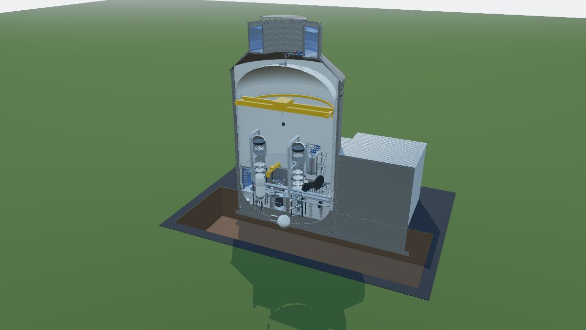
How it is arranged
Two-loop reactor coolant system: each steam generator has one hot leg from the vessel and two cold legs back to it, each with a canned-motor pump hung under the channel head. The pressurizer sits on hot leg 2.
Passive core cooling: two core makeup tanks and two accumulators inject through the direct vessel injection lines; four stages of automatic depressurization bring pressure down so the IRWST can inject by gravity; the passive RHR heat exchanger in the IRWST removes decay heat by natural circulation; recirculation screens let water flow back from the containment floor for long-term cooling.
Passive containment cooling: the steel vessel transfers heat to air rising in the annulus and to a film of water draining from the tank on the roof.
No AC power needed: the safety-related systems do their safety job on batteries and stored energy for an extended period.
Sizes are model values for a generic plant. The internal arrangement is simplified and is not any real design.
Walk through it
The guided tour in the trainer stops at each of these, highlights the equipment and explains it.
- The shield building: a concrete cylinder about 145 ft across (model value). It protects the containment and is the chimney for passive containment cooling.
- The cooling water tank on the roof. After an accident its water drains onto the dome for about 72 hours (model value).
- The steel containment vessel, about 130 ft across (model value): the pressure boundary, and the heat-transfer surface for passive cooling.
- The reactor vessel, with the core inside. Coolant enters through four inlet nozzles and leaves through two outlet nozzles.
- The core: 157 fuel assemblies, 14 ft of active fuel (model values).
- Two steam generators, about 74 ft tall (model value). The cutaway shows the tube bundle and the separators in the steam drum.
- Four canned-motor pumps hang under the steam generator channel heads. No shaft seals.
- The pressurizer holds system pressure with heaters, spray and safety valves.
- Core makeup tanks: cold borated water at reactor pressure that drains in by gravity.
- Accumulators: borated water under nitrogen that injects when pressure drops.
- The IRWST, under the operating deck: water for gravity injection and the heat sink for the passive RHR heat exchanger.
- The passive RHR heat exchanger hangs in the IRWST and cools the reactor by natural circulation.
- Automatic depressurization stages 1 to 3, in two valve modules over the pressurizer, discharge to spargers in the IRWST.
- Stage 4 squib valves on the hot legs, and squib valves on the IRWST injection lines.
- The polar crane lifts the reactor head and heavy components during outages.
- A pressurizer level transmitter, remote mounted below its taps with sloped stainless tubing, wired by conduit to a Division A cable tray.
Equipment in this building
Each item links to its entry in the equipment reference. In the trainer, click any of them to see what it does, its ratings and its safety note.
Access platform × 2Concrete foundation × 2Equipment support stand × 4Handrail × 2Lightning protection × 1Stair tower × 3Exothermic weld × 1Ground grid × 1Ground rod × 1Cable tray × 6Cable tray fitting × 10Cable tray support × 54Cables in tray × 6Conduit × 33Conduit body (LB) × 2Conduit support × 130Drop-out and conduit-to-tray fittings × 26Junction / terminal box × 3Liquidtight flexible metal conduit × 39Tray grounding conductor × 2Auxiliary building × 1Access road × 1Component supports × 4Control rod drive mechanisms × 1Main feedwater line (inside containment) × 2Main steam line (inside containment) × 2Moisture separators and dryers × 2Pressurizer × 1Pressurizer heaters × 3Reactor coolant piping × 8Reactor coolant pump (canned motor) × 4Reactor core × 1Reactor vessel × 1Reactor vessel closure head × 1Steam generator × 2Tube bundle × 2Tubesheet and divider plate × 2Accumulator × 2Air baffle × 1Air outlet (diffuser) × 1Automatic depressurization valve × 16Containment recirculation screen × 1Core makeup tank × 2IRWST screen × 1In-containment refueling water storage tank (IRWST) × 1Passive containment cooling water tank × 1Passive residual heat removal (RHR) heat exchanger × 1Sparger × 2Water distribution bucket and weirs × 1pH adjustment basket × 1Containment floors × 2Containment internal structures × 4Electrical penetration assembly × 6Equipment hatch × 2Fuel transfer tube × 2Personnel airlock × 2Refueling cavity × 1Refueling machine × 1Shield building × 1Steel containment vessel × 1Water (shown in cutaway) × 3Air-operated valve × 6Check valve × 6Motor-operated valve × 5Passive safety piping × 41Pipe support × 9Pressurizer safety valves × 1Squib valve × 6Condensate pot × 1Differential pressure transmitter × 1Instrument stand × 2Instrument tubing × 4Pressure transmitter × 1Root valve × 3Polar crane × 1
Part of a generic plant built for training. It is not any real plant or design, and sizes and ratings are model values, not design values.