Primary injection test set
High-current source driven through CT primaries. Proves CT ratio and polarity through the whole protection circuit.
Standards: IEEE C57.13
Reference entry, not built in a building yet
352 items: 203 modeled in the 3D buildings, 24 cross-references to modeled items and 125 reference entries. What each one is, what it does, typical ratings, the safety note and the standards that cover it. Values are typical for training, not design values.
Open the trainer
Float-and-vane relay in the pipe between the main tank and the conservator. Alarms on slow gas accumulation (incipient arcing or overheating) and trips on a sudden oil surge from an internal fault.
| ANSI device | 63 |
Standards: IEEE C57.12.00, Device 63
Show it in 3D: Switchyard × 3Plant site × 3
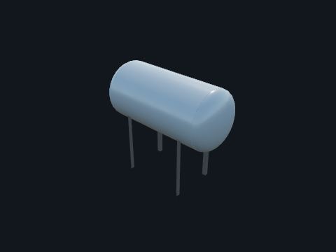
Oil reservoir mounted above the main tank, often with a rubber bladder. Keeps the main tank completely full while oil expands and contracts with temperature. It limits oil contact with air and moisture.
| Breather | Silica-gel dehydrating breather |
| Gauge | 71Q oil level |
| Where used | In this model on the 500 kV autotransformer bank, the generator step-ups, the converter transformers, the shunt reactor and the phase shifter. Most US units below EHV are sealed tanks with a nitrogen gas space instead |
Standards: IEEE C57.12.00
Show it in 3D: Switchyard × 3Plant site × 3
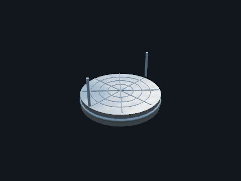
Motor-driven fans that blow air through the radiators. Adds forced-air cooling (ONAF) and raises the rating by about one third of the ONAN rating per stage: 100%, 133% and 167% (for example 20/26.7/33.3 MVA). Fans start on top-oil or winding temperature.
| Control | 49 winding temp contacts, stage 1 and stage 2 |
Standards: IEEE C57.91
Show it in 3D: Switchyard × 64Plant site × 64
Tap switch inside the transformer that is changed only with the unit off. Sets the transformer ratio for the long-term system voltage, typically in steps of 2.5 %.
Standards: IEEE C57.12.00
In the model: Modeled as Generator step-up (GSU) transformer Switchyard × 3Plant site × 3
Inside each main step-up transformer in the model; its tap positions are on the nameplate.
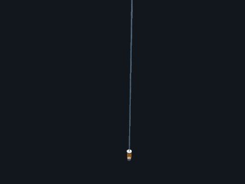
Clear canister of silica-gel beads on the conservator air line. Dries the air the conservator breathes in as the oil cools and shrinks, so moisture does not get into the transformer oil. The beads change color when they are saturated and need replacing.
| Check | Replace when about two thirds of the gel has changed color |
Standards: IEEE C57.12.00
Show it in 3D: Switchyard × 3Plant site × 3
Transformer with air or cast-resin insulation and no oil, used indoors. Supplies control-house loads and indoor equipment where oil would be a fire hazard.
Standards: IEEE C57.12.01, IEEE C57.12.91
Reference entry, not built in a building yet
Series inverter that injects voltage during sags. Protects a sensitive plant from short voltage dips.
Standards: IEEE 1159
Reference entry, not built in a building yet
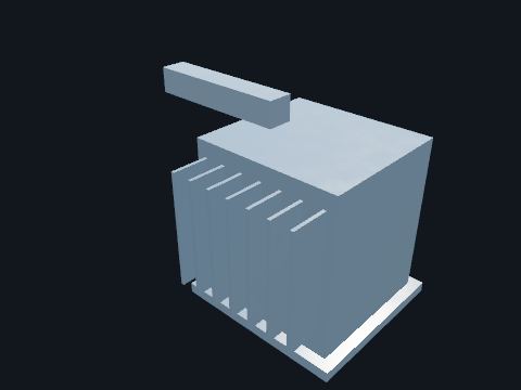
An outdoor transformer next to the turbine building. Steps the generator voltage down for the thyristor rectifiers that supply the rotor field.
| This plant | Fed from the generator main leads (public plant description); rating is a model value |
Safety. Treat it as energized whenever the generator is turning.
Standards: IEEE C57.12.00 (liquid-immersed transformers, general requirements), IEEE C57.12.90 (test code), IEEE C57.91 (loading guide), IEEE C57.104 (dissolved gas analysis), IEEE C57.152 (field testing)
Show it in 3D: Turbine building × 1Plant site × 1
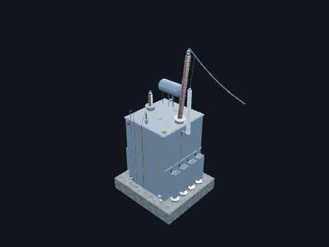
Large two-winding transformer with a delta LV winding fed by the generator and a grounded-wye HV winding tied to the grid. Raises generator voltage (15–25 kV) to transmission voltage (230–500 kV). Delta LV blocks zero-sequence current and third harmonics between the generator and the grid.
| Protection | 87T, 87U (unit overall), 63, 51G |
| Taps | De-energized tap changer (DETC) only |
| Cooling | ONAF / OFAF with oil pumps |
Safety. GSUs stay energized from the grid even when the unit is offline. Confirm the high-side breaker AND disconnects are open.
Standards: IEEE C57.12.00 (liquid-immersed transformers, general requirements), IEEE C57.12.90 (test code), IEEE C57.91 (loading guide), IEEE C57.104 (dissolved gas analysis), IEEE C57.152 (field testing), IEEE C57.116 (GSU transformers connected to generators), NFPA 804 (fire protection for advanced light water reactor plants), named only, Devices 87T, 87U, 63
Show it in 3D: Switchyard × 3Plant site × 3
Zigzag (or wye-delta) transformer connected to a delta system, usually with a neutral resistor. Creates a neutral and a ground-fault current path on an ungrounded (delta) system, so ground faults can be detected and cleared.
| ANSI | 51N on the neutral |
Safety. Without it, a ground fault on a delta system can go undetected and overvoltages build up on the healthy phases.
Reference entry, not built in a building yet
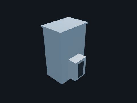
Separate oil compartment with a motor-driven selector and diverter switch. Changes transformer turns ratio while carrying load to regulate the LV bus voltage automatically.
| Range | ±10% in 32 steps typical |
| Control | 90 voltage regulating relay |
Safety. The LTC operates on its own. Block the motor drive before working on it.
Standards: IEEE C57.131 (load tap changers), Device 90
Show it in 3D: Switchyard × 4Plant site × 4
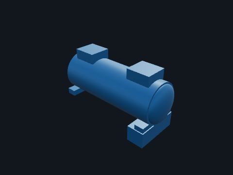
Four-pole synchronous generator on the same shaft as the high- and low-pressure steam turbines, hydrogen cooled, with water-cooled stator bars. Turns the turbine's mechanical power into three-phase power at 24 kV, synchronized to the grid at 60 Hz.
| Speed | 1,800 rpm (four-pole, 60 Hz). Large nuclear units commonly run at half speed because their low-pressure turbines have very long last-stage blades |
| This unit | 1,375 MVA, 24 kV, 0.90 pf (model value) |
| Protection | Two independent systems in the plant relay room (model value): 87G differential, 40 loss of field, 32 reverse power, 46 negative sequence, 64G stator ground (100 %), 64F field ground, 21 or 51V system backup, 24 overexcitation (volts per hertz), 59 overvoltage, 81 over and underfrequency, 78 loss of synchronism, 50/27 inadvertent energization, 60 VT fuse loss; 87U unit overall in the switchyard relay house. Device numbers per IEEE C37.2 (named only) |
Safety. Hydrogen in the generator frame is a fire and explosion hazard: no hot work near the generator or the hydrogen supply without a permit.
Standards: IEEE C50.13 (cylindrical-rotor generators), IEEE C37.102 (generator protection), Devices 87G, 40, 32, 46, 64G
Show it in 3D: Turbine building × 1Plant site × 1
Capacitors, fuses, switch and inrush reactor in a grounded cabinet. Safer near people and smaller than an open rack.
Standards: IEEE 18, IEEE 1036
Reference entry, not built in a building yet

Stainless steel nameplate with the transformer's ratings. Shows MVA, voltages, impedance, BIL, tap positions, connection diagram, oil volume and weight. It is the first stop for any engineering check.
Standards: IEEE C57.12.00 (nameplate data)
Show it in 3D: Switchyard × 7Plant site × 7
Vegetable-oil based insulating liquid with a high fire point. Replaces mineral oil to reduce fire risk and environmental impact; often qualifies for reduced spacing.
Standards: IEEE C57.147, ASTM D6871
Reference entry, not built in a building yet
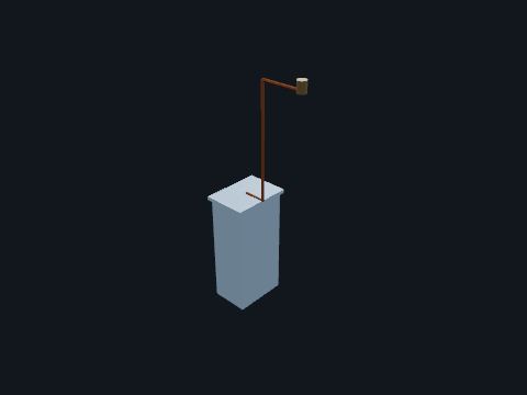
Cabinet on the tank wall holding a nitrogen cylinder, a two-stage regulator and pressure gauges, piped to the gas space above the oil. On a sealed-tank transformer the oil expands into a nitrogen blanket instead of a conservator. The regulator adds nitrogen as the oil cools and a pressure-vacuum bleeder vents the excess as it heats, so air and moisture never touch the oil. This is the usual US practice below EHV; the conservator is the alternative.
| Instruments | Pressure-vacuum gauge on the gas space (63 contacts for alarm), cylinder pressure gauge |
| Typical gas pressure | About 0.5 to 5 psig over the oil (Model value) |
Safety. Nitrogen displaces air: never enter a confined space on the tank without ventilation and gas testing.
Standards: IEEE C57.12.00 (sealed-tank oil preservation), IEEE C57.93 (installation of liquid-immersed transformers)
Show it in 3D: Switchyard × 4Plant site × 4
Gate or globe valves on the tank: bottom drain valve and top/bottom filter-press valves. Used to draw oil samples for dissolved gas analysis (DGA), to filter or process the oil, and to drain the tank.
| Test | Annual DGA oil sample is standard practice |
Safety. Never open a valve on an energized transformer except the sampling valve, with the proper procedure.
Standards: IEEE C57.12.00, IEEE C57.104 (oil sampling for DGA)
Show it in 3D: Switchyard × 7Plant site × 7
Oil-filled, oil-cooled transformer with HV and LV windings on a laminated steel core in a sealed steel tank. Changes voltage between two systems (for example 69→12.47 kV at a distribution station, 230→69 kV at a transmission station) so power moves efficiently at high voltage and is used at lower voltage. The largest and most expensive item in most substations.
| ANSI device | 87T differential, 63 sudden pressure, 26/49 temp |
| Cooling | ONAN / ONAF / ONAF (fans in two stages) |
| Impedance | 7–12% on base MVA |
| Standard | IEEE C57.12.00 |
| Weight | 40–250 tons with oil |
Safety. Treat as energized until both sides are open, grounded and tested. Oil fires burn hot: know where the containment and fire barriers are.
Reference entry, not built in a building yet
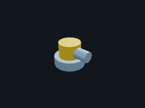
Spring-loaded valve on the tank cover with a directed discharge shroud. Vents tank pressure during an internal fault to keep the tank from rupturing, and gives a trip/alarm contact.
| ANSI | 63PRD |
Safety. It can discharge hot oil without warning. Stay clear of the shroud outlet.
Standards: IEEE C57.12.00, Device 63PRD
Show it in 3D: Switchyard × 7Plant site × 7
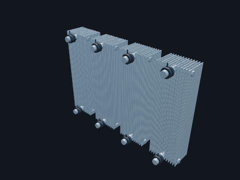
Steel panel radiators bolted to the tank through valves at top and bottom headers. Hot oil rises from the windings, passes through the radiators, cools, and sinks back into the tank. This natural thermosiphon is the ONAN rating.
| Valves | Isolation valves allow removal without draining the tank |
Standards: IEEE C57.12.00, IEEE C57.91 (cooling and loading)
Show it in 3D: Switchyard × 14Plant site × 14
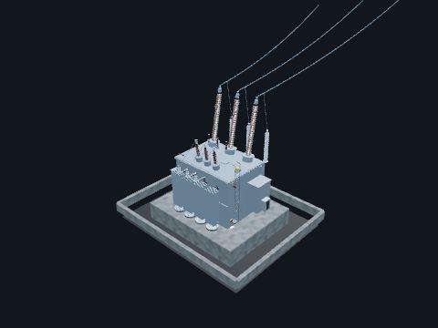
Transformer fed from a separate offsite line and sized to carry the plant's 6.9 kV buses. The second offsite circuit. If the normal supply through the unit auxiliary transformers is lost, the 6.9 kV buses transfer to the reserve auxiliary transformers.
| This plant | Two three-winding units, 70/35/35 MVA, 230 kV – 6.9 kV – 6.9 kV (model value) |
| Basis | 10 CFR 50 Appendix A, GDC 17: power from the transmission network by two physically independent circuits |
| Currents | 70 MVA at 230 kV is 176 A on the high side |
Safety. Energized from the reserve line at all times, even with the unit shut down.
Standards: IEEE C57.12.00 (liquid-immersed transformers, general requirements), IEEE C57.12.90 (test code), IEEE C57.91 (loading guide), IEEE C57.104 (dissolved gas analysis), IEEE C57.152 (field testing), NFPA 804 (fire protection for advanced light water reactor plants), named only, Devices 87, 50/51
Show it in 3D: Switchyard × 2Plant site × 2
A diesel engine driving a 6.9 kV generator, in its own building with a fuel day tank. Backs up the plant's 6.9 kV buses if both offsite circuits are lost. In a passive plant the diesels are not safety-related: the safety systems need no AC power to do their safety job.
| This plant | Two units, 4,000 kW, 6.9 kV, non-safety with augmented regulatory treatment (model value) |
Safety. Starts automatically on loss of bus voltage: never assume a stopped diesel will stay stopped.
Reference entry, not built in a building yet
Small distribution transformer fed from the station bus through fuse cutouts. Supplies the substation's own AC loads: lighting, HVAC, battery chargers, breaker heaters and motor operators, and transformer fans.
| Typical | 75–300 kVA, 208Y/120 or 240/120 V |
| Protection | Fuse cutouts on primary |
Safety. The low-voltage side can be back-fed from a portable generator. Lock out both sources.
Reference entry, not built in a building yet
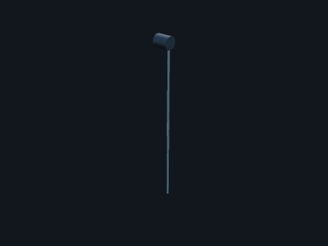
Small diaphragm relay mounted high on the tank wall, in the gas space or in the oil. Trips the transformer on a rapid rise in pressure from an internal arcing fault, the sealed-tank counterpart of the Buchholz surge trip. It ignores the slow pressure changes of normal heating and cooling.
| ANSI device | 63SP; wired to the transformer lockout 86T with the differential 87T |
Standards: IEEE C37.91 (transformer protection), Device 63SP (IEEE C37.2)
Show it in 3D: Switchyard × 4Plant site × 4

Dial gauges for top-oil temperature, winding hot-spot temperature and oil level. Give local readings and contacts for fan control, alarms and trips.
| ANSI | 26Q oil temp, 49 winding temp, 71Q oil level |
Standards: IEEE C57.12.00, Devices 26Q, 49, 71Q, 63
Show it in 3D: Switchyard × 7Plant site × 7
Series capacitor with a thyristor-controlled reactor in parallel. Varies a line's effective reactance continuously to steer power and damp oscillations.
Standards: IEEE 824
Reference entry, not built in a building yet
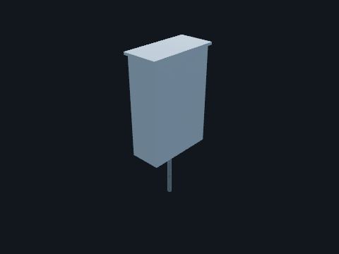
Weatherproof cabinet on the tank wall. Houses fan contactors, alarm wiring, CT shorting terminal blocks, heaters and the terminations for cables to the control house.
| Wiring | Via conduit to the cable trench |
Safety. CT secondaries land here. Never open-circuit an energized CT.
Standards: IEEE C57.12.00, IEEE C37.90
Show it in 3D: Switchyard × 7Plant site × 7
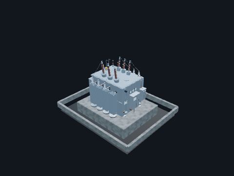
Transformer tapped off the isolated phase bus between the generator breaker and the main step-up bank. Feeds the plant's 6.9 kV buses (reactor coolant pumps, feedwater, condensate and circulating water pumps) from the generator while it runs, and from the grid back through the step-up bank when the generator breaker is open.
| This plant | Two three-winding units, 70/35/35 MVA, 24 kV – 6.9 kV – 6.9 kV (model value) |
| Currents | I = S / (√3 × V): 70 MVA at 24 kV is 1,684 A; 35 MVA at 6.9 kV is 2,929 A per winding |
| Protection | 87T differential, 51 overcurrent, 63 sudden pressure |
Safety. Energized whenever the step-up bank or the generator is live: both must be isolated before work.
Standards: IEEE C57.12.00 (liquid-immersed transformers, general requirements), IEEE C57.12.90 (test code), IEEE C57.91 (loading guide), IEEE C57.104 (dissolved gas analysis), IEEE C57.152 (field testing), NFPA 804 (fire protection for advanced light water reactor plants), named only, Devices 87, 50/51
Show it in 3D: Switchyard × 2Plant site × 2
Horns or spring whips on a disconnect contact. Move the arc away from the main contacts when opening small charging or magnetizing currents.
Standards: IEEE C37.30.1
Reference entry, not built in a building yet
Disconnect arranged to jumper around a breaker, recloser or regulator. Lets equipment be removed from service without an outage.
Standards: IEEE C37.30.1
Reference entry, not built in a building yet
Two rotating insulators per phase each carry half the blade, which opens in the middle. Low-profile disconnect; needs wider phase spacing.
Standards: IEEE C37.30.1
In the model: Modeled as Disconnect switch Switchyard × 16Plant site × 16
A type in the Disconnect switch card's Compare gallery.
Interrupter plus disconnect in one device, with lower interrupting ratings than a breaker. A cheaper, lighter alternative to a breaker for transformer protection at 69–230 kV.
| ANSI | 52 (or 89 + interrupter) |
Reference entry, not built in a building yet
Controller that times breaker closing or opening to a chosen point on the voltage wave. Cuts inrush on transformers, capacitor banks and reactors.
Standards: IEEE C37.010
Reference entry, not built in a building yet
Sand-filled fuse that forces current to zero in under a half cycle. Limits let-through energy for VTs, pad-mounts and switchgear.
Standards: IEEE C37.41, IEEE C37.47
Reference entry, not built in a building yet
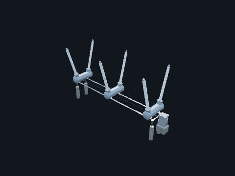
Circuit breaker with its interrupters inside grounded metal tanks filled with SF6 gas (or vacuum at distribution voltage). Interrupts load and fault current automatically when relays trip it. Disconnect switches cannot interrupt fault current; breakers, reclosers, circuit switchers and fuses can. A breaker has the highest interrupting rating of the four.
| ANSI device | 52 |
| Interrupting | 40–63 kA |
| Clearing time | 3 cycles |
| Standard | IEEE C37.04 / C37.06 |
Safety. Stored-energy springs can operate without warning. Discharge springs and block the mechanism before working on it. Check SF6 density, because arc byproducts are toxic.
Standards: IEEE C37.04 (AC high-voltage breaker ratings), IEEE C37.06 (preferred ratings), IEEE C37.09 (test procedure), IEEE C37.010 (application guide), Device 52 (IEEE C37.2), EPA 40 CFR 98 Subpart DD (SF6 reporting)
Show it in 3D: Switchyard × 9Plant site × 9
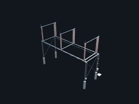
Three-pole switch with a visible blade gap, mounted on station post insulators. Isolates equipment for maintenance with a visible open point. It is operated only with no load current (after the breaker opens), except small magnetizing or charging currents.
| ANSI device | 89 |
| Types | Vertical break, center break, double end break |
Safety. NEVER open a disconnect under load: it draws an arc that can travel to ground. Verify the breaker is open first.
Standards: IEEE C37.30.1 (high-voltage air switch requirements), ANSI C37.32 (switch ratings and dimensions), Device 89, OSHA 1910.269(m) (deenergizing lines and equipment for employee protection)
Show it in 3D: Switchyard × 16Plant site × 16
Center insulator rotates the blade flat, opening two gaps in series. Higher-voltage disconnect with two breaks.
Standards: IEEE C37.30.1
In the model: Modeled as Disconnect switch Switchyard × 16Plant site × 16
A type in the Disconnect switch card's Compare gallery.
Vacuum or SF6 interrupter, often pad-mounted, that clears fault current without a full breaker. Protects underground taps and loops in distribution systems.
Standards: IEEE C37.60, IEEE C37.74
Reference entry, not built in a building yet
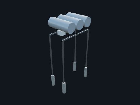
A breaker in the isolated phase bus between the generator and the step-up bank, one enclosure per phase. Opens to separate the generator from the grid while the step-up bank and unit auxiliary transformers stay energized from the 500 kV yard, so a generator trip does not take away the plant's normal power supply.
| This unit | 24 kV, 36 kA continuous (generator full load 33.1 kA) (model value) |
| Standard | IEC/IEEE 62271-37-013 (AC generator circuit breakers; replaced IEEE C37.013): named only |
Safety. Generator-voltage fault currents are very high. Work on it only inside a clearance that has isolated both the generator and the step-up bank.
Standards: IEC/IEEE 62271-37-013 (generator circuit breakers), Device 52G
Show it in 3D: Switchyard × 1Plant site × 1
Capacitor connected across each interrupter break. Divides recovery voltage evenly across multiple breaks so one chamber does not take most of the stress.
Reference entry, not built in a building yet
Blade mounted on the disconnect base that swings up to the line terminal. Grounds the de-energized line or equipment for worker protection. It is mechanically interlocked with the main blade so it cannot close when the main blade is closed.
| ANSI | 89G |
Safety. Portable protective grounds are still applied per your work procedure. The switch is not a substitute unless the procedure says so.
Standards: IEEE C37.30.1, Device 57, OSHA 1910.269(n) (grounding for protection of employees)
Show it in 3D: Switchyard × 20Plant site × 20
Single-pole switch opened one phase at a time with a hot stick. Simple isolation for low-cost bays and bypass positions.
Standards: IEEE C37.30.1
In the model: Modeled as Disconnect switch Switchyard × 16Plant site × 16
A type in the Disconnect switch card's Compare gallery.
SF6 puffer interrupter in a porcelain housing: one of two breaks per pole on the live-tank breaker. Draws and extinguishes the arc at current zero during opening. Two breaks in series share the voltage.
| Medium | SF6 at ~6–7 bar |
Reference entry, not built in a building yet
Disconnect with an attached interrupter (vacuum bottle or SF6) for load, magnetizing or line-charging current. Lets an air switch open transformer magnetizing or line charging current safely.
Standards: IEEE C37.30.1
Reference entry, not built in a building yet
Trapped-key lock system on breakers, switches and doors. Forces the safe sequence: for example, a ground switch key is released only when the disconnect is open.
Standards: IEEE C37.20.2 (switchgear interlocks)
Reference entry, not built in a building yet
Circuit breaker whose interrupters sit at line potential in porcelain housings on support columns. Same job as a dead-tank breaker (clear faults and switch load). It is common at EHV because it uses less SF6 and less steel. Needs separate freestanding CTs.
| ANSI device | 52 |
| Rating | 4000 A, 63 kA |
| Operation | Independent pole (single-pole trip for 1-ph reclosing) |
Safety. The top is energized at full line voltage. Never climb without a clearance.
Reference entry, not built in a building yet
Switch with arc chutes or whips rated to interrupt load current. Switches load without a breaker; cannot clear a fault.
Standards: IEEE C37.30.1
Reference entry, not built in a building yet
Lineup of draw-out vacuum breakers in grounded steel cubicles with separated compartments. Distributes 5–38 kV power to feeders. Breakers rack out for maintenance, giving a visible disconnect.
| Standard | IEEE C37.20.2 |
Safety. Arc-flash hazard at the front of the gear. Rack breakers remotely where available.
Reference entry, not built in a building yet
Fixed-mounted load-interrupter switches and fuses in a metal enclosure. Medium-voltage distribution where breakers are not needed.
Standards: IEEE C37.20.3
Reference entry, not built in a building yet
Metal-clad switchgear on a trailer. Temporary feeder breakers during station rebuilds.
Standards: IEEE C37.20.2
Reference entry, not built in a building yet
Lineup of motor starters and feeders in plug-in buckets. Controls motors at plants and large stations (HVAC, pumps, coolers).
Standards: NEMA ICS 18, UL 845
Reference entry, not built in a building yet
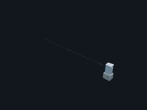
Cabinet with the spring, hydraulic or pneumatic mechanism, trip/close coils, counters and control wiring. Stores the energy to open and close the breaker in milliseconds on command from relays or SCADA.
| Control | 125 Vdc trip/close |
| Features | Anti-pump, low-gas lockout, operations counter |
Safety. Charged springs are lethal. Follow the manufacturer lockout procedure.
Standards: IEEE C37.04, IEEE C37.09
Show it in 3D: Switchyard × 9Plant site × 9
Scissor-arm contact that extends up to an overhead bus conductor. Saves space at EHV: one post per phase connects a lower bay to an upper bus.
Standards: IEEE C37.30.1
In the model: Modeled as Disconnect switch Switchyard × 16Plant site × 16
A type in the Disconnect switch card's Compare gallery.
Station fuse on a stand (expulsion or current-limiting), 34.5–138 kV class. Protects small transformers and capacitor banks where a breaker is not justified.
Standards: IEEE C37.41, IEEE C37.46
Reference entry, not built in a building yet
Compact SF6 or solid-dielectric switchgear with two loop switches and a fused or breaker tee. Loop-feeds underground distribution.
Standards: IEEE C37.74, IEC 62271-200
Reference entry, not built in a building yet
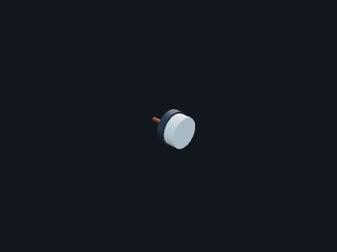
Temperature-compensated pressure gauge with alarm and lockout contacts, piped to each breaker tank or pole. Watches the amount of SF6 gas inside the breaker. If gas leaks out the breaker can no longer interrupt safely, so the monitor alarms first and then blocks the breaker from operating.
| Stages | Low-gas alarm, then trip/close lockout |
| ANSI | 63 (pressure) |
Safety. Do not operate a breaker in low-gas lockout. SF6 that has been arced forms toxic byproducts: use PPE when opening a tank.
Standards: IEEE C37.122.1 (SF6 equipment), EPA 40 CFR 98 Subpart DD, Device 63 (gas)
Show it in 3D: Switchyard × 27Plant site × 27
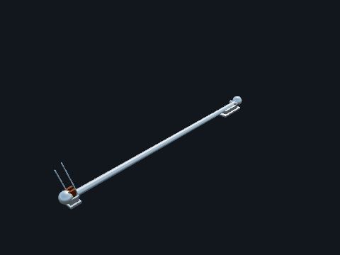
Aluminum tube blade that swings open or closed between the hinge and jaw contacts. Carries the current when closed and provides the visible air gap when open.
| Contacts | Silver-plated copper jaw fingers |
Standards: IEEE C37.30.1
Show it in 3D: Switchyard × 48Plant site × 48
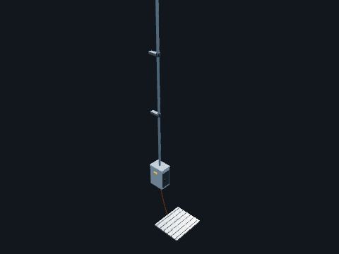
Manual worm-gear or motor operator with a vertical operating pipe and interphase linkage. Rotates the insulators to open or close all three phases together. Motor operators allow remote SCADA switching.
| Features | Padlock provisions, position indicator |
Safety. Stand on the grounded operator mat when operating. The handle is bonded to it for touch-voltage protection.
Standards: IEEE C37.30.1, OSHA 1910.269(m)
Show it in 3D: Switchyard × 32Plant site × 32
GIS or RMU switch with closed, open and grounded positions in one mechanism. Makes closing a ground on a live circuit mechanically impossible.
Standards: IEEE C37.122
Reference entry, not built in a building yet
Relay or IED function that passes a small current through the trip coil. Alarms if the trip circuit opens, so a breaker is never left unable to trip.
Standards: IEEE C37.2 (52TCM)
Reference entry, not built in a building yet
Air disconnect whose blade rotates up 90°; the most common station style. Gives a visible open gap with the least phase spacing.
Standards: IEEE C37.30.1, RUS 1724E-300
In the model: Modeled as Disconnect switch Switchyard × 16Plant site × 16
Every disconnect modeled in the switchyard is a vertical-break switch. The other styles are in the Disconnect switch card's Compare gallery.
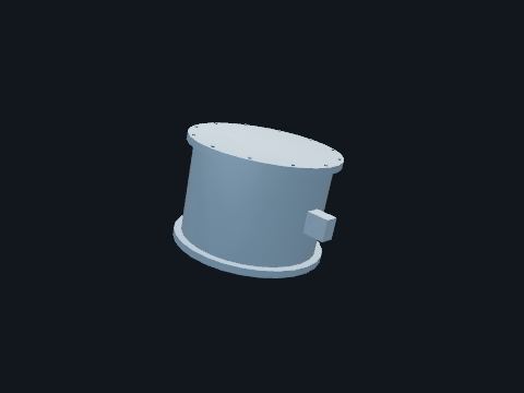
Toroidal multi-ratio CT fitted around the base of a breaker or transformer bushing. Measures primary current for protective relays and metering. CTs on both sides of the breaker overlap the protection zones so there is no blind spot.
| Ratio | Multi-ratio, e.g. 2000:5 |
| Accuracy | C400 / C800 relaying |
Safety. An open-circuited CT secondary under load develops thousands of volts. Short CTs before lifting wires.
Standards: IEEE C57.13, IEEE C37.110
Show it in 3D: Switchyard × 54Plant site × 54
Sensors on the bushing test taps that track capacitance and power factor. Gives warning of bushing insulation failure, a leading cause of transformer fires.
Standards: IEEE C57.19.00
Reference entry, not built in a building yet
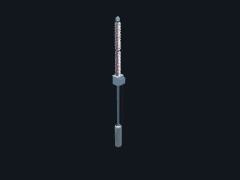
Capacitor divider stack with an electromagnetic unit (EMU) at the base. Steps line voltage down to 115/66.4 V for relays and metering, and couples power-line-carrier signals to the line.
| Accuracy | 0.3 WXYZ |
| Standard | IEEE C57.13 |
Safety. Secondary circuits are live whenever the line is. Never short a VT secondary.
Standards: IEEE C93.1 (power-line carrier coupling capacitors and CCVTs), IEEE C57.13
Show it in 3D: Switchyard × 12Plant site × 12
Oil- or gas-insulated CT on a porcelain column with primary terminals at the top. Steps line current down to 1 or 5 A for relays and revenue metering. Used where the breaker has no bushings (live tank).
| ANSI | CT |
| Accuracy | 0.3B1.8 metering / C800 relaying |
Safety. Never open-circuit a CT secondary while primary current flows.
Standards: IEEE C57.13, IEEE C37.110 (CT application for relaying)
Show it in 3D: Switchyard × 3Plant site × 3
Hall-effect sensor or shunt. Measures battery and DC system current.
Standards: IEEE 946
Reference entry, not built in a building yet
Lighter-duty arrester for distribution lines and equipment. Protects pole-mounted transformers, cutouts and cable risers.
Standards: IEEE C62.11
Reference entry, not built in a building yet
Sensor on a conductor measuring sag, tension or temperature. Lets a line carry more power when weather allows.
Standards: IEEE 738
Reference entry, not built in a building yet
Optical temperature sensor installed directly in the winding. Measures the true winding hot spot for loading decisions.
Standards: IEEE C57.91
Reference entry, not built in a building yet
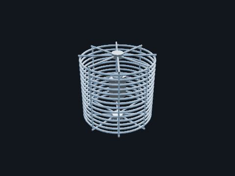
Large air-core inductor with a tuning pack, in series with the line. Passes 60 Hz power but blocks the 30–500 kHz carrier signal so relay communication stays on the line and does not leak into the station bus.
| Rating | 2000 A, 0.2–2 mH |
Standards: IEEE C93.3 (line traps)
Show it in 3D: Switchyard × 4Plant site × 4
Yard device that digitizes CT and VT signals. Sends sampled values to relays over fiber, replacing copper CT and VT wiring.
Standards: IEC 61850-9-2, IEC 61869-9
Reference entry, not built in a building yet
Instrument on the transformer that samples the oil and measures dissolved fault gases. Detects arcing, overheating and partial discharge inside the tank long before failure.
Standards: IEEE C57.104
Reference entry, not built in a building yet
Fiber-optic or Rogowski-coil current and voltage sensor with digital output. Replaces oil CTs and VTs; feeds merging units over IEC 61850 process bus.
Standards: IEC 61869-9, IEC 61850-9-2
Reference entry, not built in a building yet
One tank containing metering-class CTs and VTs. Revenue metering at a point of interconnection in one compact unit.
Standards: IEEE C57.13, ANSI C12
Reference entry, not built in a building yet
Oil-filled wound transformer with its high-voltage primary connected line-to-ground and low-voltage secondaries in a terminal box. Steps bus or line voltage down to a standard secondary, 120 V phase-to-phase (69.3 V phase-to-ground), or 115 V / 66.4 V on a 115 V base, so relays, meters, synchronizing and voltage controls can measure it. Unlike a CCVT it is a true magnetic transformer, so it is very accurate for revenue metering and has no capacitor ringing during faults.
| ANSI | IEEE C57.13, accuracy 0.3WXYZ, ZZ |
| Ratio (69 kV) | 350:1 / 600:1, 115 / 66.4 V |
| Why two numbers | 120 V is the phase-to-phase secondary; 120/√3 = 69.3 V phase-to-ground. Many relays use a 115 V base: 115/√3 = 66.4 V. A 7200:120 V unit on 12.47Y/7.2 kV is connected line-to-ground, so its 120 V is the line-to-ground value |
| Ratio (12.47 kV) | 60:1, 7200 – 120 V |
| Secondary | Fused in the terminal box |
Safety. Never short a VT secondary: it will push huge current into the short. A VT can also back-feed its primary to full voltage, so pull the secondary fuses before working on a de-energized PT.
Standards: IEEE C57.13 (instrument transformers), IEEE C57.13.3 (grounding of secondary circuits)
Show it in 3D: Switchyard × 3Plant site × 3
Meter that records harmonics, sags, swells and flicker. Documents compliance with IEEE 519 and investigates customer complaints.
Standards: IEEE 519, IEEE 1159, IEC 61000-4-30
Reference entry, not built in a building yet
High-voltage divider with a low-voltage output. Measures voltage for metering, power quality and HVDC.
Standards: IEC 61869-11
Reference entry, not built in a building yet
Air gap between two electrodes. Crude, cheap overvoltage protection; largely replaced by arresters.
Standards: IEEE C62.11
Reference entry, not built in a building yet
Highest-duty metal-oxide arrester class. Protects transformers and major equipment at 69 kV and above.
Standards: IEEE C62.11, IEEE C62.22
In the model: Modeled as Surge arrester Switchyard × 42Plant site × 42
Every arrester in the 500 kV and 230 kV switchyard is station class. The Surge arrester card gives the classes.
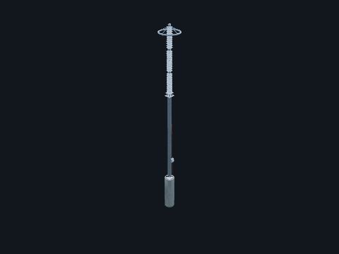
Metal-oxide varistor (MOV) blocks in a polymer or porcelain housing, connected line-to-ground. Stays non-conducting at normal voltage but conducts heavily during lightning or switching surges, clamping voltage below equipment BIL.
| Standard | IEEE C62.11 |
| Location | Line entrances and transformer terminals |
Safety. A failed arrester can explode. Stay out from under arresters during storms.
Standards: IEEE C62.11 (metal-oxide surge arresters), IEEE C62.22 (arrester application)
Show it in 3D: Switchyard × 42Plant site × 42
Capacitor from line to ground at a motor or generator terminal. Slows surge rise time to protect rotating-machine insulation.
Standards: IEEE C62.21
Reference entry, not built in a building yet
Counter and milliammeter in the arrester ground lead. Counts discharge operations and shows leakage current. Rising leakage means the arrester is degrading.
Standards: IEEE C62.11
Show it in 3D: Switchyard × 15Plant site × 15
Low-voltage surge suppressor on AC, DC and communication circuits. Protects electronics in the control house.
Standards: UL 1449, IEEE C62.41
Reference entry, not built in a building yet
All-aluminum (AAC) or aluminum alloy (AAAC) stranded conductor. Strain bus and jumpers where high conductivity matters more than strength.
Standards: ASTM B231, ASTM B399
In the model: Modeled as Flexible jumper (strain bus) Switchyard × 192Plant site × 192
The flexible jumper and strain bus card names AAC and ACSR.
Aluminum strands around a steel core. Strain bus and line conductor with high strength-to-weight.
Standards: ASTM B232, IEEE 738
In the model: Modeled as Transmission line conductor Switchyard × 4Plant site × 8
The transmission line conductor in the model is ACSR; the flexible jumper card names AAC and ACSR for strain bus.
Two or more subconductors per phase held apart by spacers. Raises ampacity and reduces corona at EHV.
Standards: IEEE 738
Reference entry, not built in a building yet
Cable laid inside a bus tube. Damps wind-induced (aeolian) vibration of long bus spans.
Standards: IEEE 605
Reference entry, not built in a building yet

Cast aluminum clamp on top of the post insulator. Holds the bus pipe. Fixed fittings anchor the bus; slip fittings let it slide for thermal expansion.
Standards: IEEE 605 (bus design in air-insulated substations), RUS 1724E-300 Table 4-7 / ANSI C37.32 (clearances)
Show it in 3D: Switchyard × 84Plant site × 84
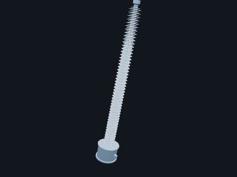
Insulating bushing that carries the conductor from the tank to the external terminal. Connects the breaker or recloser to the bus jumpers while insulating it from the grounded tank.
| Material | Porcelain or silicone composite |
Standards: IEEE C57.19.00 / C57.19.01 (bushings)
Show it in 3D: Switchyard × 54Plant site × 54
Insulated cables in a ventilated tray-like enclosure. High-ampacity connection between transformer and switchgear.
Standards: IEEE C37.23
Reference entry, not built in a building yet
Stress-control termination at the end of shielded power cable. Transitions underground cable to an overhead connection, controlling electrical stress where the cable shield ends.
Reference entry, not built in a building yet
Smooth metal ring on EHV hardware. Spreads the electric field to stop corona and radio noise.
Standards: IEEE 605
In the model: Modeled as Grading (corona) ring Switchyard × 15Plant site × 15
Same device: see Grading (corona) ring.
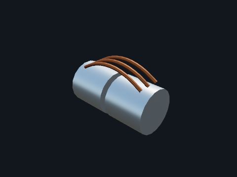
Sleeve joint with flexible braid jumpers across the gap. Lets long bus runs expand and contract (about 23 mm per 10 m per 100 °C for aluminum) without loading the insulators.
Standards: IEEE 605 (bus design in air-insulated substations), RUS 1724E-300 Table 4-7 / ANSI C37.32 (clearances)
Show it in 3D: Switchyard × 6Plant site × 6

Stranded aluminum or ACSR conductor between equipment terminals. Connects equipment to equipment and equipment to bus. The slack allows for thermal movement and seismic displacement.
| Typical | 795–1590 kcmil AAC / ACSR |
Standards: IEEE 605, IEEE 738 (conductor ampacity)
Show it in 3D: Switchyard × 192Plant site × 192
Long SF6 or gas-mixture insulated transmission line in pipes. High-capacity underground or tunnel transmission.
Standards: IEC 62271-204
Reference entry, not built in a building yet
Line from a power plant's collector substation to the utility point of interconnection. Delivers plant output to the grid.
Standards: NESC
Reference entry, not built in a building yet
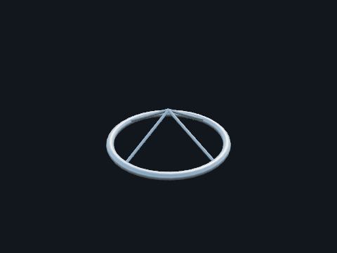
Aluminum toroid at the top of EHV insulators and arresters. Smooths the electric field, preventing corona and radio noise, and evens voltage distribution along the stack.
Standards: IEEE C62.11, IEEE 1427
Show it in 3D: Switchyard × 15Plant site × 15
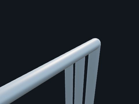
Each phase conductor inside its own grounded aluminum enclosure, air-insulated. Carries very high generator current (10–30 kA) from the generator to the GSU. Phase isolation makes phase-to-phase faults very unlikely: a fault would have to be phase-to-enclosure first.
| Cooling | Natural or forced air |
Safety. Enclosure currents are induced. Do not break enclosure bonds.
Standards: IEEE C37.23 (metal-enclosed bus)
Show it in 3D: Switchyard × 1Turbine building × 2Plant site × 3
One-piece porcelain or silicone-rubber insulator. Replaces cap-and-pin strings; lighter and vandal resistant.
Standards: ANSI C29.11
Reference entry, not built in a building yet
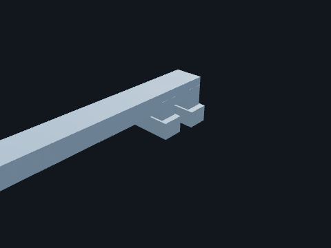
Three insulated bus bars in one ventilated steel enclosure. Carries 6.9 kV power from each transformer winding to the medium-voltage switchgear in the annex building.
| This unit | 3,000 A, 6.9 kV (winding full load 2,929 A) (model value) |
| Standard | IEEE C37.23 (metal-enclosed bus): named only |
Safety. Energized whenever its transformer is.
Standards: IEEE C37.23 (metal-enclosed bus), named only
Show it in 3D: Switchyard × 1Plant site × 1
Shielded cable with EPR or XLPE insulation and a copper concentric neutral or tape shield. Carries power underground between units.
| Standard | ICEA S-94-649 |
Reference entry, not built in a building yet
Copper or aluminum bars on standoff insulators. Main bus inside switchgear and switchboards.
Standards: IEEE C37.20.2, IEEE 605
Reference entry, not built in a building yet
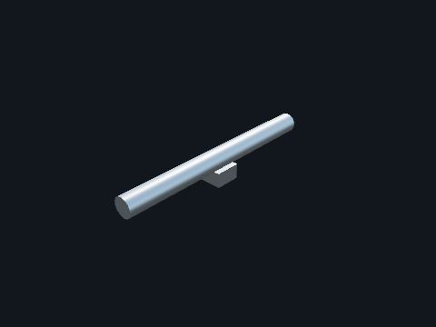
Schedule 40 aluminum pipe (6063-T6) supported on station post insulators. Collects and distributes power between all circuits at one voltage. Rigid bus is short-circuit strong and needs little maintenance.
| Sizing | Ampacity, short-circuit force, span deflection, corona |
| Standard | IEEE 605 |
Safety. The bus is energized by any circuit connected to it. Know every source.
Standards: IEEE 605 (bus design in air-insulated substations), RUS 1724E-300 Table 4-7 / ANSI C37.32 (clearances)
Show it in 3D: Switchyard × 36Plant site × 36
Metal-enclosed bus with phases separated by barriers (or not). Connects transformers to medium-voltage switchgear and generators.
Standards: IEEE C37.23
Reference entry, not built in a building yet

Steel or OPGW wire strung above the phase conductors. Intercepts lightning so it does not hit the phases. OPGW also carries fiber for relay and SCADA communications.
Standards: IEEE 998 (direct stroke shielding), IEEE 80 (grounding)
Show it in 3D: Switchyard × 5Plant site × 9
Small porcelain insulators for low-voltage and distribution racks. Support secondary and distribution conductors.
Standards: ANSI C29.3, ANSI C29.5
Reference entry, not built in a building yet
Solid porcelain column with sheds and galvanized end caps. Supports bus and switch parts and insulates them from grounded steel. Sheds lengthen the creepage path for rain and contamination.
| Standard | ANSI C29.9 (TR numbers) |
| Rating | Voltage class, BIL, cantilever strength |
Safety. Chipped or cracked posts can fail under fault forces.
Standards: ANSI C29.9 (station post insulators), IEEE 1427
Show it in 3D: Switchyard × 276Plant site × 276
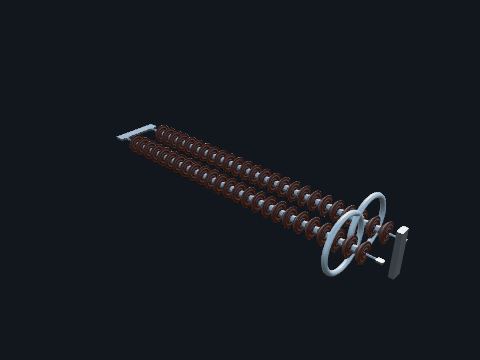
String of porcelain bells or a polymer rod insulator in tension. Insulates the line conductor from the dead-end structure while holding the full line tension.
Standards: ANSI C29.11 / C29.13 (composite insulators), IEEE 1427
Show it in 3D: Switchyard × 36Plant site × 36
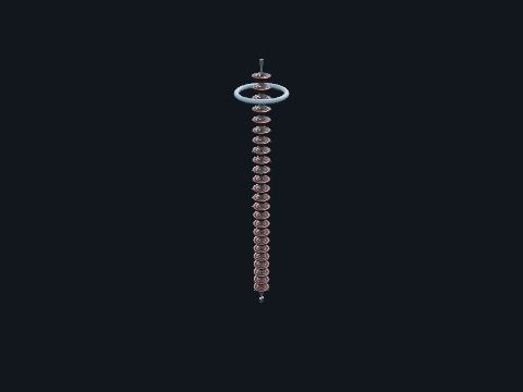
Vertical insulator string on a transmission tower. Supports the weight of the conductor and insulates it from the tower.
Standards: ANSI C29.2 (suspension insulators), IEEE 1427
Show it in 3D: Switchyard × 12Plant site × 39

Welded or bolted fitting that taps a cable off the rigid bus. Connects each bay's jumper to the main bus.
Standards: IEEE 605, NEMA CC 1 (connectors)
Show it in 3D: Switchyard × 57Plant site × 57
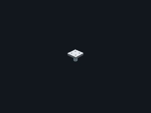
Bolted aluminum pad or compression lug. Makes the high-current connection between conductors and equipment terminals (NEMA 2- or 4-hole pads).
| Check | Infrared scan for hot connections |
Standards: NEMA CC 1 (electric power connectors), IEEE 605
Show it in 3D: Switchyard × 294Plant site × 294
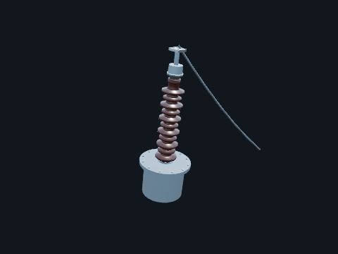
Insulated conductor through the tank wall. Porcelain or composite outside, oil/paper condenser core inside. Brings the winding leads out of the grounded tank safely. Marked H1–H3 (HV), X1–X3 (LV), H0/X0 (neutral).
| Test tap | Power factor / capacitance test point |
| Standard | IEEE C57.19.01 |
Safety. A cracked or oil-leaking bushing can fail violently. Report low oil level in the sight glass immediately.
Standards: IEEE C57.19.00 / C57.19.01 (bushings)
Show it in 3D: Switchyard × 37Plant site × 37
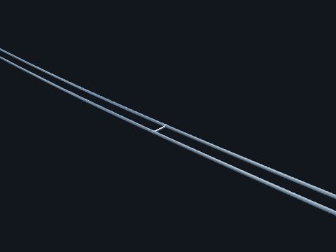
Stranded aluminum conductor steel reinforced (ACSR). Carries power into and out of the station. At EHV, bundled subconductors reduce corona.
Safety. Induced voltage from parallel lines can be lethal even on de-energized lines. Ground on both sides of the work.
Standards: IEEE 738 (conductor temperature and ampacity), NESC Section 23 (clearances) and Section 25 (loads)
Show it in 3D: Switchyard × 4Plant site × 8
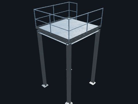
A steel grating platform with guardrails, toe boards and a stair. Gives access to instruments and valves: the pressurizer instruments, and the depressurization valve modules above the pressurizer.
| Walking surfaces | OSHA 29 CFR 1910 Subpart D: guardrails 42 in top rail and 21 in mid rail [1910.29(b)], toe boards [1910.29(k)], stairs [1910.25] |
Safety. Falls: stay inside the guardrails.
Standards: OSHA 29 CFR 1910 Subpart D (walking-working surfaces)
Show it in 3D: Containment × 2Plant site × 2
Threaded rods cast in the foundation with leveling nuts. Fasten structure base plates to the concrete.
Standards: ASTM F1554
In the model: Modeled as Concrete foundation Switchyard × 403Turbine building × 2Containment × 2Plant site × 444
Cast into the modeled foundations, with the nuts showing on every base plate.
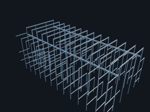
Columns, crane girders, roof girders, floor beams and bracing. Carries the roof, siding, floors and the crane. The first bay next to the auxiliary building is designed so it cannot fall onto the nuclear island in an earthquake.
| This plant | Main area: braced steel frame, non-seismic (the public plant description gives eccentrically braced frames; the model draws simple X-bracing); first bay: seismic Category II (public plant description); member sizes are model values |
Standards: AISC 360 (structural steel buildings), named only, Regulatory Guide 1.29 (non-Category I structures whose failure could affect Category I items)
Show it in 3D: Turbine building × 1Plant site × 1
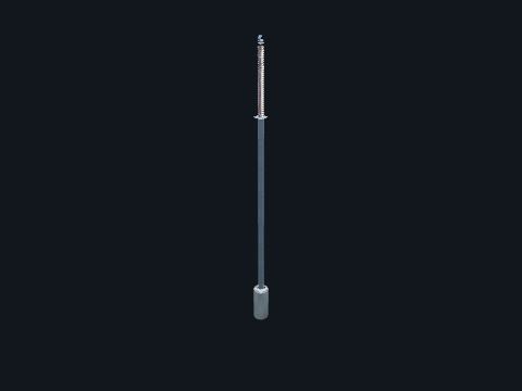
Galvanized pipe pedestal with a station post insulator on top. Holds the rigid bus at design height and spacing.
Standards: IEEE 605 (bus design in air-insulated substations), RUS 1724E-300 Table 4-7 / ANSI C37.32 (clearances), ANSI C29.9 (station post insulators)
Show it in 3D: Switchyard × 132Plant site × 132
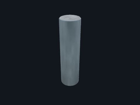
Drilled pier or spread footing with anchor bolts. Transfers dead, wind, ice, short-circuit and seismic loads into the soil.
| Design | Geotech report, ACI 318 |
Standards: ACI 318 (structural concrete), ASCE MOP 113, IEEE 691 (transmission structure foundations)
Show it in 3D: Switchyard × 403Turbine building × 2Containment × 2Plant site × 444
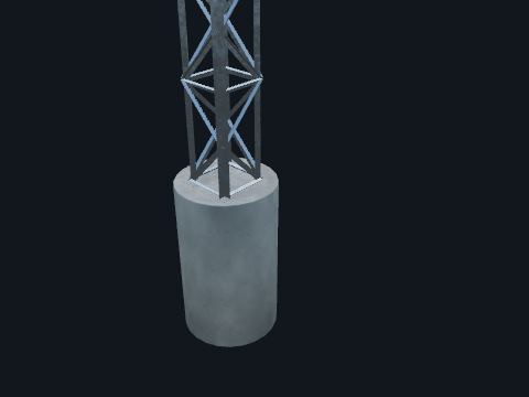
Steel lattice or tubular H-frame with columns and a beam. Terminates the incoming or outgoing line, taking full conductor and shield wire tension so the station bus sees no line pull.
| Design | ASCE 113, NESC loading |
Standards: ASCE MOP 113 (substation structure design), NESC Section 25 (loads), IEEE 693 (seismic, where required), ASCE 7 (loads) and AISC 360 (steel), named only, ASTM A123/A123M (hot-dip galvanizing), NESC Rule 250 (loading)
Show it in 3D: Switchyard × 12Plant site × 12
Concrete cylinder cast in a drilled hole. Carries moment and uplift from structures and equipment stands.
Standards: ACI 318, ASCE MOP 113
In the model: Modeled as Concrete foundation Switchyard × 403Turbine building × 2Containment × 2Plant site × 444
The modeled foundations: drilled piers under switchyard stands and structures, slabs under transformers, and the nuclear island basemat.
Lightweight modular towers. Rebuild a line temporarily after storm damage.
Standards: IEEE 1070
Reference entry, not built in a building yet
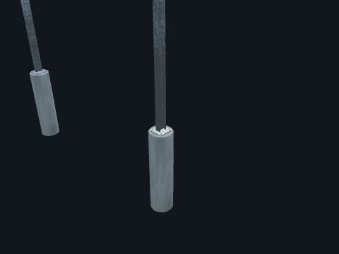
Galvanized steel column or frame anchored to a foundation. Raises equipment so live parts meet the required height above grade for that voltage (NESC Rule 124 sets the code minimum; utilities commonly design to the RUS 1724E-300 Table 4-7 heights used by the Measure tool).
| Clearance | NESC Table 124-1 |
Standards: ASCE MOP 113 (substation structure design), NESC Section 25 (loads), IEEE 693 (seismic, where required), ASCE 7 (loads) and AISC 360 (steel), named only, ASTM A123/A123M (hot-dip galvanizing)
Show it in 3D: Switchyard × 181Turbine building × 1Containment × 4Plant site × 186
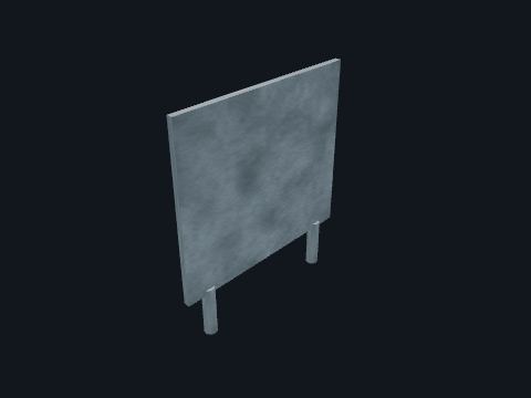
Reinforced-concrete or block wall between oil-filled transformers that stand close together. Keeps a fire in one unit from spreading to the next. A barrier is needed when units are closer than the separation distance for their oil volume.
| Separation without a barrier | Mineral oil (not an approved less-flammable fluid): under 500 gal, 5 ft (1.5 m); 500 to 5,000 gal, 25 ft (7.6 m); over 5,000 gal, 50 ft (15.2 m), measured to the closest edge of containment |
| Barrier | 2-hour fire rated, extending 1 ft (0.3 m) vertically and 2 ft (0.6 m) horizontally beyond the transformer components that could be pressurized by an electrical fault: bushings, pressure-relief vents, radiators and tap changer enclosures |
| Basis | FM Global Data Sheet 5-4 (July 2019, interim revision Oct 2020), Table 8 and section 2.3.1.3. IEEE 979 and NFPA 850 give similar guidance; insurer and utility standards govern the actual design |
| This model | Wall top is above the tank, conservator, radiators and pressure-relief device. On EHV units the bushings reach far higher; how far a wall must go up beside them is set by the insurer and utility standard |
Standards: IEEE 979 (substation fire protection), FM Global DS 5-4, NFPA 804 (fire protection for advanced light water reactor plants), named only
Show it in 3D: Switchyard × 2Plant site × 2
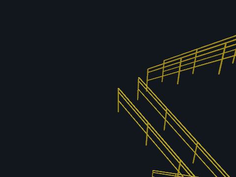
Top rail, mid rail and toe board on posts. Guards open edges and floor openings.
| Rule | Guardrail top rail 42 in, plus or minus 3 in, above the walking surface [OSHA 29 CFR 1910.29(b)(1)]; on stairs, a stair rail system at least 42 in high and a handrail 30 to 38 in above the tread nosing [OSHA 29 CFR 1910.29(f)(1)] |
Standards: OSHA 29 CFR 1910.29 (fall protection systems)
Show it in 3D: Turbine building × 2Containment × 2Plant site × 4
Steel shaft with helical plates screwed into the soil. Quick foundation for walls and light structures, including retrofits.
Standards: ICC-ES AC358
Reference entry, not built in a building yet
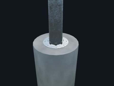
Tall tapered steel pole with an air terminal on top. Creates a protected zone for equipment below by intercepting direct lightning strikes.
| Method | Rolling sphere, IEEE 998 |
Standards: IEEE 998 (direct stroke shielding), ASCE MOP 113 (substation structure design)
Show it in 3D: Switchyard × 25Plant site × 25
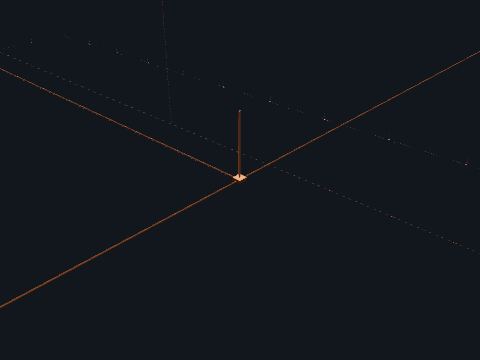
Short air terminals around the roof edges and across the roof, joined by copper conductors that run down the outside walls to ground rods. Gives a lightning strike a planned, low-impedance path to the ground grid, so the current does not pass through the building steel, the siding or the cables inside.
| Guidance | Regulatory Guide 1.204 Rev. 1, Guidelines for Lightning Protection for Production and Utilization Facilities (February 2024, ML23241A957); it endorses IEEE 665-1995, IEEE 666-2007, IEEE 1050-2004 and IEEE C62.23-2017 (named only) |
| Standard | NFPA 780 (named only) |
| Shown | Terminal spacing, heights, conductor sizes and the number of down conductors are model values |
Safety. During a thunderstorm stay off the roof and away from down conductors and ground rods.
Standards: Regulatory Guide 1.204 Rev. 1 (February 2024, ML23241A957), guidelines for lightning protection for production and utilization facilities, IEEE 665-1995, IEEE 666-2007, IEEE 1050-2004 and IEEE C62.23-2017 (endorsed by RG 1.204), named only, NFPA 780 (installation of lightning protection systems), named only
Show it in 3D: Turbine building × 1Containment × 1Plant site × 2
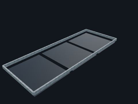
Concrete curb and liner around the transformer, filled with stone. Captures oil if the tank leaks or ruptures so it cannot reach soil or waterways. Most utilities contain large oil-filled equipment. SPCC (40 CFR 112) applies to a facility whose aboveground oil storage capacity exceeds 1,320 US gal (counting containers of 55 gal or more) and that could reasonably be expected to discharge oil to navigable waters or adjoining shorelines (112.1). For oil-filled operational equipment it then requires general secondary containment (112.7(c)) or the 112.7(k) alternative (inspections, a contingency plan and committed manpower). The largest-container-plus-freeboard sizing of 112.8(c)(2) is for bulk storage containers, not oil-filled operational equipment; the familiar "110%" figure is a state or industry convention, not text in Part 112. The 112.7(k) alternative is not approved by anyone: the owner implements and documents it.
| Design basis | Oil volume of the largest unit plus rainfall and any firewater (IEEE 980 practice). A 25-yr, 24-h storm is a common rainfall basis taken from EPA SPCC guidance; check state and local rules |
| Drain | Oil-stop valve or oil/water separator |
Standards: IEEE 980 (oil spill containment), 40 CFR 112 (SPCC)
Show it in 3D: Switchyard × 5Plant site × 5
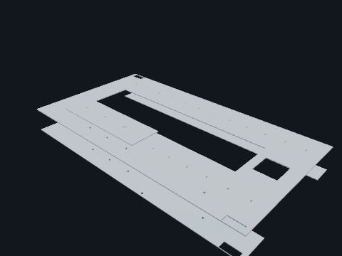
Concrete floors at grade, the mezzanine, the operating floor and the deaerator floor in the heater bay. Working levels for operations and maintenance; the operating floor is the laydown area during an outage.
| This plant | Mezzanine El. 123 ft, operating floor El. 160 ft, deaerator floor El. 192 ft (model values) |
Safety. Floor openings, hatches and open edges: guardrails or covers are required [OSHA 29 CFR 1910.28].
Standards: OSHA 29 CFR 1910 Subpart D (walking-working surfaces)
Show it in 3D: Turbine building × 1Plant site × 1
Shallow reinforced concrete pad. Supports transformers, control houses and heavy equipment.
Standards: ACI 318
In the model: Modeled as Concrete foundation Switchyard × 403Turbine building × 2Containment × 2Plant site × 444
The modeled foundations: drilled piers under switchyard stands and structures, slabs under transformers, and the nuclear island basemat.

Steel stairs with landings between floors, a stair rail and a handrail on each side of every flight. Access between grade, the mezzanine, the operating floor and the deaerator floor; also an escape route.
| Rule | Flights with at least 3 treads and 4 risers get stair rail systems and handrails [OSHA 29 CFR 1910.28(b)(11)]; standard stairs are set at 30 to 50 degrees from horizontal [OSHA 29 CFR 1910.25(c)(1)] |
Standards: OSHA 29 CFR 1910.25 (stairways)
Show it in 3D: Turbine building × 1Containment × 3Plant site × 4
Tall A-frames or lattice columns supporting tensioned conductor bus. Carries bus across a yard with fewer supports than rigid bus.
Standards: ASCE MOP 113
In the model: Modeled as Dead-end structure Switchyard × 12Plant site × 12
Every dead-end structure in the switchyard carries strain bus.
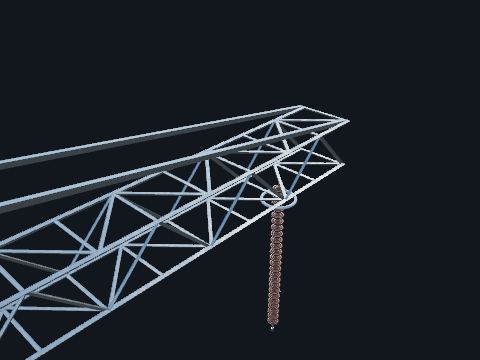
Steel lattice tower with crossarms and insulator strings. Carries the line away from the station. The first span is usually slack-strung to limit tension on the dead-end.
Standards: ASCE MOP 113 (substation structure design), NESC Section 25 (loads), IEEE 693 (seismic, where required), ASCE 7 (loads) and AISC 360 (steel), named only, ASTM A123/A123M (hot-dip galvanizing), ASCE 10 (lattice steel structures)
Show it in 3D: Switchyard × 4Plant site × 13
Tapered round or polygonal steel pole. Dead-ends, masts and take-off structures with a small footprint.
Standards: ASCE/SEI 48
In the model: Modeled as Lightning mast Switchyard × 25Plant site × 25
Every lightning mast in the switchyard is a tubular steel pole.
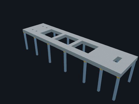
A thick reinforced concrete deck on spring units, carried by a steel frame. Holds the turbine-generator in line and isolates its vibration from the building.
| This plant | Spring-mounted concrete deck on a structural steel frame that is part of the turbine building (public plant description); sizes are model values |
Standards: ACI 351.3R (foundations for dynamic equipment), named only
Show it in 3D: Turbine building × 1Plant site × 1
Pointed rod on a structure or building. Intercepts lightning strokes; NFPA 780 style for buildings.
Standards: NFPA 780
Reference entry, not built in a building yet
Tuned reactor between neutral and ground. Cancels the capacitive ground-fault current so arcing faults extinguish themselves.
Standards: IEEE C57.32
Reference entry, not built in a building yet
Buried conductor run out from a structure. Lowers surge impedance to ground at line entrances and towers.
Standards: IEEE 80
Reference entry, not built in a building yet
Rod or electrode reaching low-resistivity soil far below grade. Lowers grid resistance where surface soil is rocky or dry.
Standards: IEEE 80, IEEE 81
Reference entry, not built in a building yet

Molecular copper-to-copper weld made with a graphite mold and powder charge. Joins grid conductors permanently. It cannot loosen like a mechanical connector and holds up to corrosion and fault current better than bolted clamps.
| Use | Grid crossings, rod connections and below-grade taps where a permanent molecular joint is wanted |
Standards: IEEE 80 (AC substation grounding), IEEE 837 (permanent grounding connections)
Show it in 3D: Switchyard × 1Turbine building × 1Containment × 1Plant site × 1

Flexible copper braid from the gate leaf to the grounded gate post. Keeps the swinging gate bonded to the fence and grid. Hinges are not a reliable electrical connection.
Standards: IEEE 80 (fence grounding), NESC Rule 92E
Show it in 3D: Switchyard × 2Plant site × 2

Compression C-tap below grade or 2-hole compression lug above. Joins the ground risers to the grid and to the equipment.
Standards: IEEE 80 (AC substation grounding), IEEE 837 (permanent grounding connections)
Show it in 3D: Switchyard × 1Plant site × 1
Conductive backfill around grid conductors and rods. Lowers resistance in high-resistivity soil.
Standards: IEEE 80
Reference entry, not built in a building yet

Mesh of bare copper conductor buried about 18 in under the whole yard, extending past the fence. It runs around foundations, not through them: a loop around each pad or oil pit, a jog around a single footing, and a dip under each cable trench. Gives a low-impedance path for fault current. More importantly, it keeps step and touch voltages safe during a fault by making the whole yard rise together.
| Standard | IEEE 80 |
| Typical | 4/0 Cu, 3–8 m spacing |
| Resistance | Often <1 Ω for transmission stations |
Safety. Stolen or broken ground connections make touch voltages lethal. Report missing copper immediately.
Standards: IEEE 80 (AC substation grounding), IEEE 837 (permanent grounding connections), IEEE 81 (ground system testing), NESC Rule 93 / Section 9 (grounding)
Show it in 3D: Switchyard × 1Turbine building × 1Containment × 1Plant site × 1

Copper conductor from the grid up to each structure and piece of equipment. Bonds all metal to the grid so it cannot sit at a different voltage than the ground a worker stands on. Major apparatus gets two risers to separate grid conductors.
Standards: IEEE 80 (AC substation grounding), IEEE 837 (permanent grounding connections), IEEE 81 (ground system testing), NESC Rule 93 / Section 9 (grounding)
Show it in 3D: Switchyard × 1Plant site × 1

Copper-clad steel rod driven vertically into the soil. Reaches deeper, lower-resistivity soil and stabilizes grid resistance across seasons. Rods are placed mostly on the perimeter where current density is highest.
| Typical | 5/8 or 3/4 in × 10 ft |
Standards: IEEE 80 (AC substation grounding), IEEE 837 (permanent grounding connections), IEEE 81 (ground system testing), NESC Rule 93 / Section 9 (grounding)
Show it in 3D: Switchyard × 1Turbine building × 1Containment × 1Plant site × 1
Inspection well over a ground rod. Lets crews measure grid resistance and check connections.
Standards: IEEE 81
Reference entry, not built in a building yet
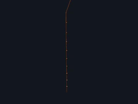
Heavy copper conductor from the X0/H0 neutral bushing to the ground grid. On a solidly grounded system it ties the wye neutral straight to the grid, so ground faults draw enough current for the relays to see quickly and the voltage stays referenced to earth. Resistance- or reactance-grounded systems put a resistor or reactor in this path on purpose, to limit ground-fault current; their relays are set for that lower current.
| Size | Often 500 kcmil Cu or 2 × 4/0 |
| Monitoring | Neutral CT for 51N / 87N |
Safety. It carries current during unbalance and faults. Never disconnect it while energized.
Standards: IEEE C62.92, IEEE 80
Show it in 3D: Switchyard × 3Plant site × 3
Inductor between a neutral and ground. Limits ground-fault current while keeping the system effectively grounded.
Standards: IEEE C57.32
Reference entry, not built in a building yet
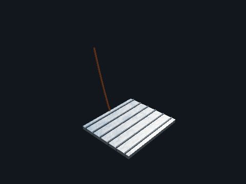
Steel grating at the switch operating handle, bonded to the handle and to the ground grid. Keeps the operator's hands and feet at nearly the same voltage if a fault happens while the switch is being operated. Stand on the mat whenever you work the handle.
| Bond | Flexible braid to the operating pipe, plus a grid riser |
Safety. Always stand on the mat when operating. Report a missing or broken bond before you operate.
Standards: IEEE 80 (operator platforms), OSHA 1910.269(n), IEEE 1246 (temporary protective grounding)
Show it in 3D: Switchyard × 16Plant site × 16
Joint between two cable lengths. Connects cable runs longer than one reel.
Standards: IEEE 404
Reference entry, not built in a building yet
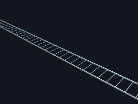
Steel ladder-type tray: two side rails joined by rungs, in 12 ft straight sections joined by splice plates, with factory fittings at every turn. Carries power, control and instrument cables. Power and instrument cables run in separate trays, and each safety division has its own trays, kept apart from the others.
| Sizes shown | 24 in × 6.188 in rail (power) and 12 in × 4.188 in rail (instrumentation) steel ladder, rungs on 9 in centers, hot-dip galvanized (catalog dimensions) |
| Separation | Regulatory Guide 1.75 Rev. 3 (endorses IEEE 384-1992) |
| Standard | NEMA VE 1-2017 (metal cable tray): named only |
Safety. Trays are not walkways or ladders.
Standards: NEMA VE 1 (metal cable tray), named only, Regulatory Guide 1.75 Rev. 3 / IEEE 384 (division separation), NEC Article 392 where the NEC applies
Show it in 3D: Switchyard × 1Turbine building × 4Containment × 6Plant site × 11

A solid steel divider strip fastened to the rungs along the middle of the tray and through its fittings. Splits one tray into two compartments, so the medium-voltage cables (6.9 kV here) and the low-voltage cables (600 V) never lie together: a fault or fire in one group is less likely to damage the other, and both can share one tray route (typical practice).
| Shown | Tray P1 in the turbine building, from the annex feed tee to the south mezzanine. The medium-voltage side is the half toward the feed; the north leg east of the tee carries 480 V feeders only and has no barrier |
| Height | The tray loading depth (model value) |
| Drop-outs | Each feeder leaves the tray over the rail on its own side of the barrier |
| Standards | NEMA VE 1 and NFPA 70 (NEC) Article 392, named only; the NEC does not cover utility generating installations (90.2), so this is typical practice |
Standards: NEMA VE 1 (metal cable tray systems, includes barrier strips), named only, NFPA 70 (NEC) Article 392 (cable trays), named only; typical practice here (the NEC does not cover utility generating installations, 90.2)
Show it in 3D: Turbine building × 2Plant site × 2
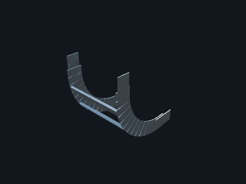
A factory-made tray section that turns or splits the run: horizontal bends, vertical inside and outside bends and tees, each with short straight tangents and splice plates. Turns the run without kinking the cables. The fitting radius is chosen so the largest cable in the tray stays above its minimum bending radius, so trays are never field-mitered at a corner (typical practice).
| Shown | 24 in radius on the 24 in power trays, 12 in radius on the 12 in instrument trays, 3 in tangents (catalog dimensions) |
| How radius is measured | Horizontal fittings to the inside rail, vertical fittings to the rung surface (catalog) |
| Supports | Within 2 ft of each fitting end (NEMA VE 2 installation guidelines, named only) |
Safety. Trays are not walkways or ladders.
Standards: NEMA VE 1 (metal cable tray and fittings), named only, NEMA VE 2 (cable tray installation guidelines), named only
Show it in 3D: Turbine building × 14Containment × 10Plant site × 24
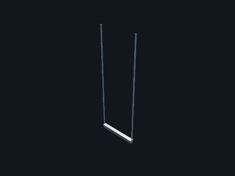
Strut-channel trapezes hung on threaded rods, riser frames and floor stands. Carry the trays: within 2 ft of each fitting end and no more than 12 ft apart, so each span stays inside the tray load rating.
| Spacing source | NEMA VE 2 installation guidelines (named only); tray load rating to a 12 ft span (NEMA VE 1, named only) |
Standards: NEMA VE 2 (cable tray installation guidelines), named only
Show it in 3D: Switchyard × 1Turbine building × 151Containment × 54Plant site × 206
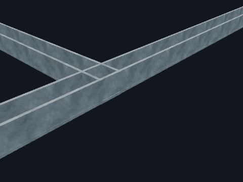
Precast concrete U-channel with removable covers. Routes control and low-voltage cable from yard equipment to the control house and makes future additions easy.
Standards: NESC Part 3 (underground lines), IEEE 525 (cable design and installation in substations), NEC Chapter 3 where the NEC applies
Show it in 3D: Switchyard × 1Plant site × 1

Power, control or instrument cables laid on the tray rungs and following the fittings. Carry power and signals between equipment. Instrument cables are kept out of the power trays so noise from power circuits does not reach the signals.
| Shown | 6.9 kV shielded and 600 V power cables in the 24 in trays; shielded twisted-pair instrument cables in the 12 in trays (model value) |
| Drawn as | One bed about a third of the tray depth (model value) |
Safety. Do not step on, pull or cut cables in a tray: medium-voltage cables can be energized.
Standards: Regulatory Guide 1.75 Rev. 3 / IEEE 384 (division separation), IEEE 383 (qualifying cables and splices for nuclear facilities), named only
Show it in 3D: Turbine building × 4Containment × 6Plant site × 10

Rigid galvanized steel conduit in 10 ft threaded lengths with couplings and factory elbows. Carries cables from the tray to a device: 1 in to each transmitter, 2 in to the 480 V vacuum pump motors, 3 in and 4 in to the 6.9 kV pump motors (into a hub on the motor terminal box).
| Sizes | 1, 2, 3 and 4 in rigid metal conduit, 1.315 to 4.500 in OD (catalog dimensions) |
| Support | Within 3 ft of each box or fitting and every 10 ft (typical practice, following NFPA 70 (NEC) 2020, 344.30; the NEC itself does not cover utility generating installations, 90.2) |
Standards: NESC Part 3 (underground lines), IEEE 525 (cable design and installation in substations), NEC Chapter 3 where the NEC applies, ANSI C80.1 (rigid steel conduit), named only
Show it in 3D: Switchyard × 1Turbine building × 27Containment × 33Plant site × 61
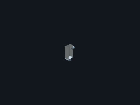
A cast fitting with a gasketed removable cover: the conduit enters one end and leaves through the back. Makes a tight 90° turn and gives a pull point, so cable can be pulled without too many bends in one run.
| Shown | 1 in LB, about 6.00 × 2.88 × 1.75 in (catalog dimensions) |
| Pull points | No more than 360° of bends between pull points (typical practice, following NFPA 70 (NEC) 2020, 344.26) |
Standards: UL 514A (metallic outlet boxes and conduit bodies), named only, NFPA 70 (NEC) 2020, 344.26 (bends between pull points) where the NEC applies
Show it in 3D: Turbine building × 5Containment × 2Plant site × 7
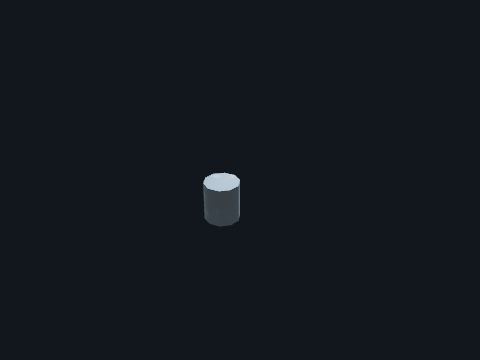
Threaded coupling or PVC-to-RGS adapter right at grade. Joins the above-grade steel stub-up to the below-grade run and seals the joint.
Standards: NESC Part 3 (underground lines), IEEE 525 (cable design and installation in substations), NEC Chapter 3 where the NEC applies
Show it in 3D: Switchyard × 1Plant site × 1

Factory-bent 90° long-radius fitting: PVC-coated rigid steel where conduit leaves the ground, Sch 40 PVC below grade. Turns the conduit from vertical to horizontal (and around corners to the trench) without kinking the cable. A big bend radius keeps pulling tension and sidewall pressure low so the cable jacket is not damaged.
| Typical radius | 24–36 in for 2–4 in conduit |
| NEC | Max 360° of bends between pull points (NEC 344.26 / 352.26) |
| Coating | PVC-coated RGS at the soil-air line to stop corrosion |
Standards: NESC Part 3 (underground lines), IEEE 525 (cable design and installation in substations), NEC Chapter 3 where the NEC applies
Show it in 3D: Switchyard × 1Plant site × 1
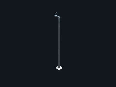
Strut-channel stanchions, trapezes and arms with conduit clamps. Hold rigid conduit within 3 ft of each box or fitting and every 10 ft (typical practice, following NFPA 70 (NEC) 2020, 344.30).
Standards: NFPA 70 (NEC) 2020, 344.30 (securing and supporting) where the NEC applies
Show it in 3D: Turbine building × 93Containment × 130Plant site × 223

Multi-conductor shielded 600 V cable. Carries CT and VT secondaries, trip and close circuits, alarms and DC power between equipment and relays.
| Typical | #10 for CT circuits, #12–#14 control |
Standards: IEEE 525, IEEE 1185 (cable installation), ICEA S-58-679 (control cable color code)
Show it in 3D: Switchyard × 1Plant site × 1
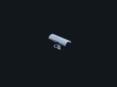
Where cable leaves the tray for a conduit: a radiused drop-out plate over the side rail, a clamp holding the conduit to the tray, and an insulated grounding bushing on the conduit end. Lets the cable leave the tray without bending sharply over a rail edge, holds the conduit in place and protects the cable insulation at the conduit opening.
| Shown | Catalog fittings on each feeder and signal conduit |
Standards: NEMA VE 1 (cable tray fittings and accessories), named only
Show it in 3D: Turbine building × 26Containment × 26Plant site × 52
PVC conduits encased in red-dyed concrete. Protects underground power cables mechanically and thermally. The red color warns anyone digging.
Safety. Call 811 before digging near a station.
Reference entry, not built in a building yet
Glass fibers in a protective jacket. Carries relay, SCADA and process-bus signals immune to EMI and GPR.
Standards: IEEE 525
Reference entry, not built in a building yet
Small precast or polymer box at grade. Pull point for smaller conduit runs.
Standards: ANSI/SCTE 77
Reference entry, not built in a building yet
XLPE-insulated transmission cable with a metallic sheath. Underground transmission lines and GIS connections.
Standards: AEIC CS9, IEEE 575
Reference entry, not built in a building yet

A steel box with terminal blocks and a gasketed cover, on a stand, a wall or a strut frame. Terminates field wiring and joins it to the cables that run on to the control or protection panels: in the switchyard, CT and VT secondary wiring into conduit to the trench; in the plant, the cables from a group of valves or instruments where their riser conduit ends.
Standards: NEMA 250 (enclosures), IEEE 525
Show it in 3D: Switchyard × 22Containment × 3Plant site × 25
Flexible steel conduit with a PVC jacket. Final connection to vibrating equipment such as transformer fans.
Standards: NEC Article 350
Reference entry, not built in a building yet
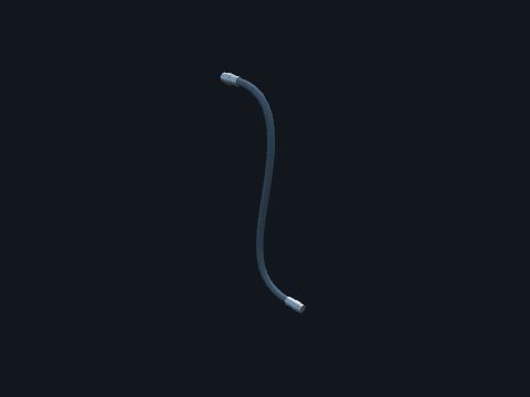
A spiral steel core with a liquidtight plastic jacket, with liquidtight connectors at both ends. Makes the last short connection to a 480 V motor or an instrument, so vibration and small movements do not stress the rigid conduit and the device can be removed for maintenance.
| Shown | 2 in to the vacuum pump motors, 1/2 in to the transmitters (catalog dimensions) |
| Rule | NFPA 70 (NEC) 2020, Article 350 (typical practice) |
Standards: UL 360 (liquidtight flexible metal conduit), named only, NFPA 70 (NEC) 2020, Article 350 where the NEC applies
Show it in 3D: Turbine building × 20Containment × 39Plant site × 59
Precast concrete vault for cable pulling and splicing. Breaks long duct bank runs into pullable lengths.
Standards: IEEE 525
Reference entry, not built in a building yet
Yard cabinet where control cables from several devices land on terminal blocks. Reduces home-run cables to the control house.
Standards: IEEE 525
Reference entry, not built in a building yet
Shielded cable with EPR or XLPE insulation. Collector circuits, feeder exits and transformer connections.
Standards: ICEA S-94-649, IEEE 576
Reference entry, not built in a building yet
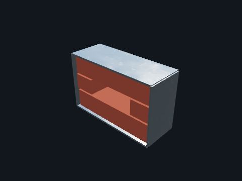
A sealed opening where a tray or conduit passes through a fire-rated wall: a steel sleeve frame filled with a tested firestop system around the cables. Keeps the wall's fire rating where cables pass through, so a fire cannot travel along the cables from one area to the next.
| Shown | Power and instrument trays through the turbine building wall to the annex building (model value) |
| Fire protection | Regulatory Guide 1.189 Rev. 5; NFPA 804 named only |
| Firestop test | ASTM E814: named only |
Standards: Regulatory Guide 1.189 Rev. 5 (fire protection), ASTM E814 (fire tests of penetration firestop systems), named only, NFPA 804, named only
Show it in 3D: Turbine building × 2Plant site × 2
Rigid nonmetallic conduit. Below-grade and duct bank raceway.
Standards: NEC Article 352, UL 651
Reference entry, not built in a building yet
Galvanized steel threaded conduit. Above-grade and stub-up raceway with physical protection.
Standards: NEC Article 344, UL 6
In the model: Modeled as Conduit Switchyard × 1Turbine building × 27Containment × 33Plant site × 61
The modeled conduit: rigid galvanized steel to the instruments and pump motors in containment, and stub-ups in the switchyard.
Load-break or dead-break elbow for pad-mounted equipment. Lets cables be connected and parked safely.
Standards: IEEE 386
Reference entry, not built in a building yet
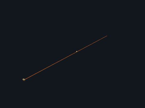
A bare stranded copper conductor laid along each power tray and clamped to every tray section and fitting. Makes the tray system one continuous ground path back to the source, so a cable fault to the tray clears quickly and the tray never sits at a dangerous voltage. It also bonds across splice plates, which can loosen or corrode (typical practice).
| Shown | In every power tray, on the rungs beside one rail, with bronze clamps at each 12 ft section and each fitting; a jumper bonds a branch run across its tee |
| Size | Model value |
| Standards | IEEE 1100 and NFPA 70 (NEC) Articles 250 and 392, named only (typical practice) |
Safety. Treat the tray grounding conductor as part of the safety ground: do not cut or disconnect it while the tray is in service.
Standards: IEEE 1100 (powering and grounding electronic equipment), named only, NFPA 70 (NEC) Articles 250 and 392 (grounding and bonding, cable trays), named only; typical practice here (90.2)
Show it in 3D: Turbine building × 2Containment × 2Plant site × 4
Precast concrete or FRP lid. Protects cables and makes a walking surface. Covers lift off for pulling new cable.
Safety. Covers are heavy. Use a lifting tool and two people.
Standards: NESC Part 3 (underground lines), IEEE 525 (cable design and installation in substations), NEC Chapter 3 where the NEC applies
Show it in 3D: Switchyard × 1Plant site × 1
Panelboards for station service AC and 125 Vdc. Distribute and protect the station's auxiliary power circuits.
Standards: NEC Articles 408, 480, IEEE 946 (DC auxiliary power systems)
Show it in 3D: Switchyard × 1Plant site × 1
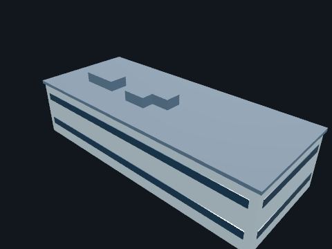
Office and training buildings outside the plant fence. Offices, classrooms and the plant-specific simulator where operators train.
| Simulator | Licensed operators train and are examined on a simulator that matches the plant (10 CFR 55.46) |
Show it in 3D: Plant site × 2
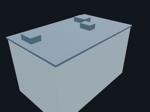
A steel and reinforced concrete building beside the nuclear island and the turbine building. Houses the control support area, the non-safety 6.9 kV and 480 V switchgear and a hot machine shop. Shown as massing; X-ray makes it see-through.
| This plant | Next to the auxiliary building and the turbine building; the part next to the nuclear island is seismic Category II (public plant description); size is a model value |
Safety. Switchgear rooms: arc flash and shock hazards; enter only with your escort.
Standards: Regulatory Guide 1.29 (non-Category I structures whose failure could affect Category I items), NFPA 804 (fire protection for advanced light water reactor plants), named only
Show it in 3D: Switchyard × 1Plant site × 2
Panel of labeled alarm windows. Shows which alarm operated and in what order.
Standards: IEEE C37.1
In the model: Modeled as Protective relay panel Switchyard × 24Plant site × 24
On the switchyard relay panel elevation sheet.
Switch that moves station service from a failed source to a backup. Keeps battery chargers, heaters and lights on when one station-service source is lost.
Standards: UL 1008
Reference entry, not built in a building yet
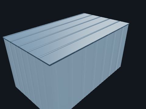
The building that wraps around one side of the shield building on the same basemat. Shown here for context. It houses the control room, fuel handling and spent fuel pool, and the safety-related electrical rooms.
Standards: 10 CFR 50 Appendix A, GDC 2, ACI 349 (nuclear safety-related concrete structures), named only, AISC N690 (nuclear steel structures), named only, Regulatory Guide 1.29 (seismic design classification)
Show it in 3D: Containment × 1Plant site × 1
Rectifier that turns station AC into regulated DC. Carries the normal DC load and keeps the battery on float charge.
Standards: IEEE 946 (DC auxiliary power systems), IEEE 485
Show it in 3D: Switchyard × 1Plant site × 1
Exhaust fan and air flow sensor for the battery room. Keeps hydrogen from charging below dangerous levels.
Standards: IEEE 484, NFPA 1
Reference entry, not built in a building yet
Pistol-grip trip–neutral–close switch with red and green lamps. Local breaker control from the panel.
Standards: IEEE C37.2
In the model: Modeled as Protective relay panel Switchyard × 24Plant site × 24
On the switchyard relay panel elevation and DC schematic sheets.
Gas extinguishing system for relay and communication rooms. Puts out fires without water damage to electronics.
Standards: NFPA 2001
Reference entry, not built in a building yet
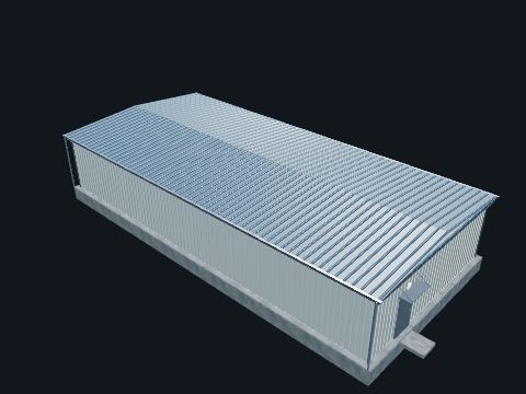
Pre-engineered building with HVAC. Houses protection and control: relays, SCADA, communications, the DC battery and the AC/DC panels.
Safety. Batteries give off hydrogen. Ventilation and no-smoking rules apply.
Standards: IEEE 1127, NFPA 70 (building wiring), IBC (building code)
Show it in 3D: Switchyard × 1Plant site × 1
Monitor on the ungrounded DC system (device 64). Alarms on a first ground so it can be found before a second ground causes a false trip.
Standards: IEEE 946, IEEE C37.2 (64)
In the model: Modeled as AC / DC distribution panels Switchyard × 1Plant site × 1
A function of the modeled DC panel and battery charger (device 64).
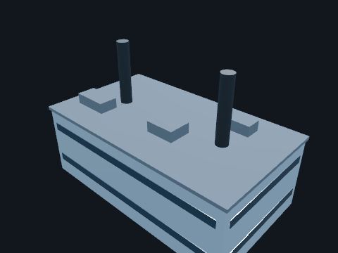
A building on its own foundation, away from the nuclear island, with two exhaust stacks. Houses the two standby diesel generators that back up the 6.9 kV buses.
| This plant | Two standby diesel generators; not safety-related, separate foundation at a distance from the nuclear island (public plant description) |
Safety. Diesels start automatically on loss of bus voltage. Noise, hot exhaust and fuel.
Standards: NFPA 37 (stationary combustion engines), named only
Show it in 3D: Plant site × 1
Battery-backed fixtures and lit exit signs. Lets people leave the building safely in a power loss.
Standards: NFPA 101
Reference entry, not built in a building yet

Self-contained emergency eyewash. Required wherever battery electrolyte can splash into eyes.
Standards: OSHA 1910.151(c), ANSI Z358.1 (eyewash equipment)
Show it in 3D: Switchyard × 1Plant site × 1
Panel monitoring smoke and heat detectors in the control house. Alarms locally and to SCADA; may release clean-agent suppression.
Standards: NFPA 72
Reference entry, not built in a building yet

A small building with the fire pumps next to the fire water tanks. Pressurizes the fire protection water system.
| Size | Model value |
Standards: NFPA 20 (stationary fire pumps), named only
Show it in 3D: Plant site × 1
Wall-mounted air conditioner and heater. Keeps electronic relays and batteries within their temperature limits.
Standards: IEEE 1127, ASHRAE 90.1 (where applied)
Show it in 3D: Switchyard × 1Plant site × 1
Hand-reset multi-contact relay. Trips and blocks closing of every breaker in a zone until someone inspects and resets it.
Standards: IEEE C37.2 (86)
In the model: Modeled as Protective relay panel Switchyard × 24Plant site × 24
Drawn on the DC schematic and the relay panel elevation sheets of the switchyard (device 86).
Digital relay with protection, metering, recording and communications. The modern protection device: one IED replaces many single-function relays.
Standards: IEEE C37.90, IEC 61850
In the model: Modeled as Protective relay panel Switchyard × 24Plant site × 24
The relays on every modeled panel are microprocessor relays; the panel elevation sheet names them by device number.
Alkaline cells with a long life and good low-temperature performance. Station battery where temperature or reliability favors NiCd.
Standards: IEEE 1106, IEEE 1115
Reference entry, not built in a building yet
Wall-mounted breaker panel. Distributes 208/120 V or 480/277 V station service and DC circuits.
Standards: UL 67, NEMA PB 1
In the model: Modeled as AC / DC distribution panels Switchyard × 1Plant site × 1
Part of the modeled AC / DC distribution panels in the switchyard relay house.
Panel with microprocessor relays, test switches, lockout relays and indication. Watches CT and VT signals and trips breakers within cycles when it sees a fault in its zone (lines 21/87L, transformer 87T, bus 87B, breaker failure 50BF).
| ANSI | 21, 50/51, 67, 79, 86, 87 |
Safety. Opening a CT test switch in the wrong order can open-circuit a CT. Follow the test procedure.
Standards: IEEE C37.90 (relays and relay systems), NERC PRC-005 (protection system maintenance), IEEE C37.2 (device numbers)
Show it in 3D: Switchyard × 24Plant site × 24
A steel-framed building next to the nuclear island. Processes and stores low-level radioactive waste (spent resins, filters and dry active waste) until it is shipped for disposal.
| This plant | Steel framed; low-level waste processing and storage (public plant description); size is a model value |
Safety. Radiological areas inside are posted under 10 CFR 20.1902; enter only on a radiation work permit.
Standards: 10 CFR 20 (radiation protection), Regulatory Guide 1.143 (radioactive waste management systems)
Show it in 3D: Plant site × 1

Remote terminal unit or substation automation computer with communications gear. Sends status and analogs to the control center and executes remote open/close commands.
| Protocols | DNP3, IEC 61850 |
Standards: IEEE 1815 (DNP3), IEC 61850, IEEE C37.1 (SCADA and automation systems)
Show it in 3D: Switchyard × 1Plant site × 1
Diesel or propane engine-generator set. Second station-service source for long outages.
Standards: NFPA 110
Reference entry, not built in a building yet
Lead-acid or NiCd cells on a rack: 60 cells for 125 Vdc. The station's lifeline. It powers relays and breaker trip coils even when all AC is lost. Sized by the IEEE 485 duty-cycle method; an 8-hour duty cycle is a common design basis (remote stations often use 12 to 24 hours), ending with enough capacity to still trip and close breakers.
| Standard | IEEE 485 sizing, IEEE 450 maintenance |
| This plant | The switchyard relay house battery, 125 Vdc (model value). The plant's safety-related DC is separate: four 250 Vdc divisions, A to D, on the auxiliary one-line |
Safety. Hydrogen gas and sulfuric acid. Use face shield, gloves and insulated tools. An eyewash station is required.
Standards: IEEE 485 (battery sizing), IEEE 450 / 1188 (maintenance and testing), OSHA 1910.151(c) (eyewash near electrolyte), NEC Article 480 (storage batteries)
Show it in 3D: Switchyard × 1Plant site × 1
Knife switches in CT and VT circuits on the relay panel. Isolate a relay for testing; CT test switches short the CT before opening.
Standards: IEEE C37.90
In the model: Modeled as Protective relay panel Switchyard × 24Plant site × 24
On the switchyard relay panel elevation sheet.
Water spray piping and nozzles around a large transformer, with a detection system. Cools and contains an oil fire; common at plants and some critical stations.
Standards: NFPA 15, NFPA 850
Reference entry, not built in a building yet

An insulated steel rolling door at the east end of the turbine building. Lets trucks into the bay under the equipment hatch, where the crane lowers parts.
Show it in 3D: Turbine building × 1Plant site × 1
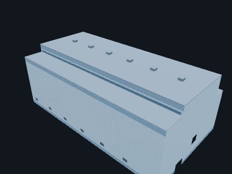
A steel-framed building with metal siding that houses the turbine-generator, condenser, moisture separator reheaters and the feedwater train. Keeps the turbine island out of the weather and carries the crane. It is not safety-related. The turbine shaft points at the nuclear island, so a blade or disk failure would throw fragments to the sides, away from safety-related structures.
| This plant | About 387 ft by 210 ft, roof about 144 ft above grade (model values); two superstructures on a common basemat, on a foundation separate from the nuclear island (public plant description) |
| Turbine missiles | Favorable orientation: potential missiles are directed 90° away from safety-related structures (public plant description); GDC 4 and Regulatory Guide 1.115, named only |
Safety. Noise, heat, rotating machinery, high-energy steam and hydrogen.
Standards: 10 CFR 50 Appendix A, GDC 4 (environmental and dynamic effects, including missiles), Regulatory Guide 1.115 (protection against turbine missiles), Regulatory Guide 1.29 (non-Category I structures whose failure could affect Category I items), NFPA 804 (fire protection for advanced light water reactor plants), named only
Show it in 3D: Switchyard × 1Turbine building × 1Plant site × 1
Battery-backed AC supply for computers and communications. Keeps SCADA, networking and HMI running through AC outages.
Standards: IEEE 944
Reference entry, not built in a building yet
Sealed lead-acid cells with recombination valves. Smaller station batteries needing little maintenance.
Standards: IEEE 1187, IEEE 1188
Reference entry, not built in a building yet
A steel building for spare parts and materials. Stores parts, tools and materials outside the power block.
Show it in 3D: Plant site × 2
A building with filters and demineralizers. Treats raw water to the purity the plant systems need and fills the demineralized water storage tank.
| Size | Model value |
Safety. Treatment chemicals: follow the chemical labels and safety data sheets.
Standards: NUREG-0800 SRP 9.2.3 (demineralized water makeup system)
Show it in 3D: Plant site × 1

Heavy-duty drive into the yard. Allows delivery of transformers and cranes for maintenance.
Standards: RUS 1724E-300 (site design)
Show it in 3D: Switchyard × 1Turbine building × 1Containment × 1Plant site × 9
LED flood light on a pole. Lights the yard for night switching and emergency work.
Standards: NESC Rule 111 (illumination of stations), IEEE 1127 (lighting impact)
Show it in 3D: Switchyard × 4Plant site × 4
Concrete-filled steel pipes. Protect equipment from vehicle impact.
Reference entry, not built in a building yet

4–6 in of clean crushed stone over the yard. High resistivity raises foot contact resistance, which cuts step and touch current. It also controls weeds and drainage.
| Resistivity | ≥3000 Ω·m wet |
Standards: IEEE 80 (surface layer resistivity)
Show it in 3D: Switchyard × 1Plant site × 1
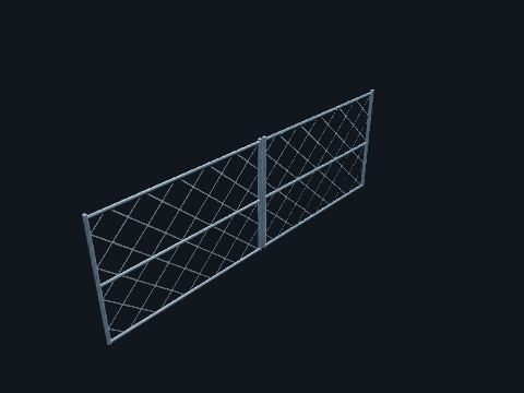
Double swing gate. Access for vehicles and crews. It is locked, grounded and bonded with a flexible jumper.
Standards: NESC Rule 110A, IEEE 80
Show it in 3D: Switchyard × 1Plant site × 1
Fabric layer under the crushed rock. Keeps subgrade soil from mixing into the rock surface layer.
Standards: RUS 1724E-300
Reference entry, not built in a building yet
Asphalt parking with striped stalls. Employee and visitor parking outside the plant fence.
Show it in 3D: Plant site × 2
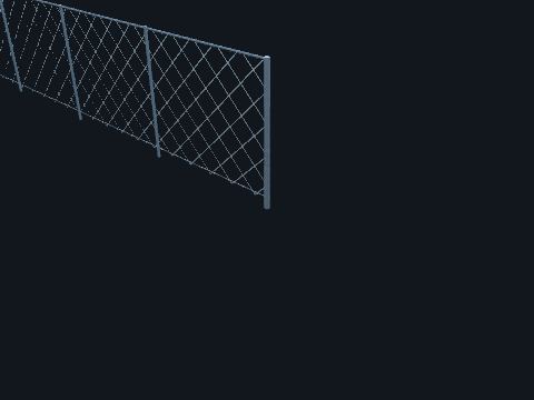
A chain-link fence around the power block. Shown only as an ordinary fence. Plant physical security is required by 10 CFR Part 73 and is deliberately not modeled on this site.
Standards: 10 CFR Part 73 (physical protection): named only, not modeled
Show it in 3D: Plant site × 1
Absorptive or reflective barrier around a transformer. Reduces transformer hum at the property line.
Standards: IEEE 1127
Reference entry, not built in a building yet
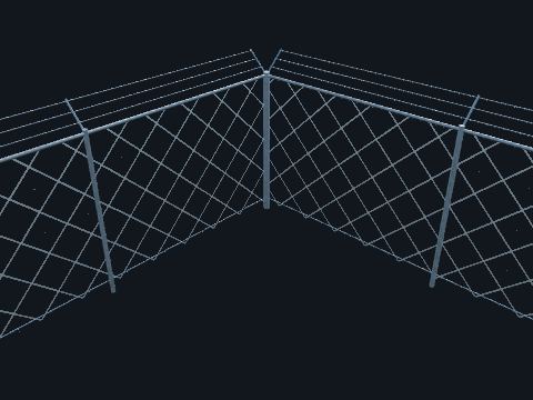
Chain-link fence with barbed wire on 45° arms. Keeps the public away from energized equipment. It is grounded to the grid because it can see touch voltage during a fault.
| NESC 110A | Fence at least 7 ft (2.13 m) overall, barbed wire included, plus the Table 110-1 safety clearance zone to live parts |
| Typical practice | 7 ft fabric + 1 ft of 3-strand barbed wire = 8 ft |
| Grid | Extends ~3 ft outside the fence |
Safety. Never leave the gate open and unattended.
Standards: NESC Rule 110A (fences, at least 7 ft), IEEE 1119-1988 (fence safety clearances; withdrawn, named for history only), IEEE 80 (fence grounding)
Show it in 3D: Switchyard × 1Plant site × 1
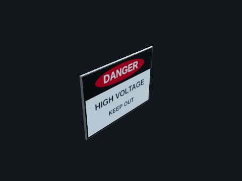
ANSI Z535-style DANGER HIGH VOLTAGE sign. Warns the public. NESC Rule 110A requires safety signs at the entrances and on the sides of the fence; check the edition in force for exact placement. The signal word and layout follow ANSI Z535 practice and are not wording the NESC prescribes.
Standards: NESC Rule 110A (signs), ANSI Z535.2 / Z535.4 (safety signs), OSHA 1910.145
Show it in 3D: Switchyard × 33Plant site × 33
Grading, ditches and pipes that move water off the yard. Keeps the crushed rock surface dry and the site from flooding.
Standards: RUS 1724E-300
Reference entry, not built in a building yet
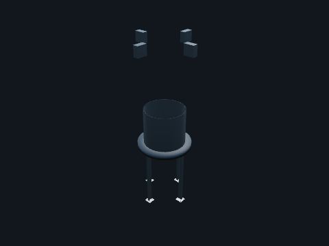
Heavy steel supports for the reactor coolant system: pads under the reactor vessel inlet nozzles, pinned columns and lateral bumpers for the steam generators, a skirt on a ring girder and columns under the pressurizer. Carry the weight of the vessels and hold them against earthquake loads, while letting the loops grow and shrink with temperature.
| This plant | Arrangement and sizes are model values |
| Code | ASME BPVC Section III, Division 1, Subsection NF (supports): named only |
Safety. Heavy steel at height next to hot, radioactive equipment.
Standards: ASME Section III, Subsection NF (component supports), named only, AISC N690 (safety-related steel structures), named only
Show it in 3D: Containment × 4Plant site × 4
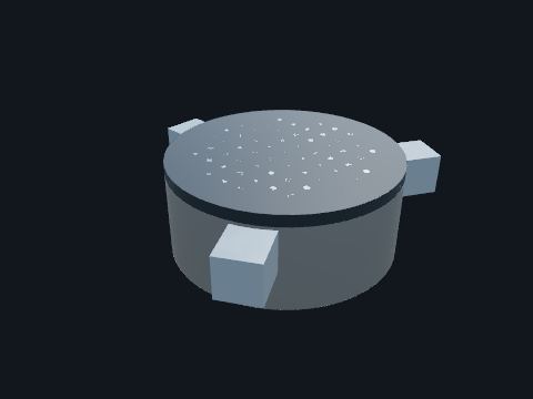
Tall pressure housings on the closure head, inside an integrated head package with shroud, cooling and cable supports. Move the control rods in and out of the core. On a reactor trip they release, and the rods drop in by gravity.
| This plant | 69 drive mechanism penetrations (model value) |
Standards: ASME BPVC Section III, Division 1 (pressure housings), named only, 10 CFR 50 Appendix A, GDC 26 (reactivity control systems) and GDC 29 (anticipated operational occurrences)
Show it in 3D: Containment × 1Plant site × 1
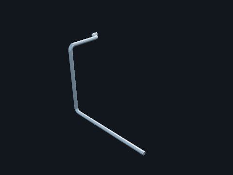
Insulated carbon steel pipe from the containment wall to a steam generator feedwater nozzle. Returns feedwater to the steam generator. It comes in through a welded sleeve from the feedwater isolation valve in the auxiliary building.
| This plant | Two lines, about 20 in (model value) |
| Code | ASME BPVC Section III, Class 2 inside containment: named only |
Safety. High-energy line: hot water at high pressure flashes to steam if it leaks.
Standards: NUREG-0800 SRP 10.4.7 (condensate and feedwater system), Regulatory Guide 1.26 Rev. 6 (quality group classification), ASME Section III, named only
Show it in 3D: Containment × 2Plant site × 2
Large insulated pipe from a steam generator outlet nozzle across to the containment wall. Carries steam toward the turbine. It leaves containment through a welded sleeve in the vessel and an opening in the shield building wall, and continues to the main steam isolation valve in the auxiliary building.
| This plant | Two lines, about 36 in OD (model value) |
| Code | ASME BPVC Section III, Class 2 inside containment: named only |
Safety. High-energy line: steam at steam generator pressure and temperature.
Standards: NUREG-0800 SRP 10.3 (main steam supply system), Regulatory Guide 1.26 Rev. 6 (quality group classification), ASME Section III (Class 2 inside containment), named only
Show it in 3D: Containment × 2Plant site × 2
Swirl-vane separators and chevron dryers in the steam drum. Remove water droplets so dry steam goes to the turbine.
Show it in 3D: Containment × 2Plant site × 2
A tall vessel, about half water and half steam, connected to a hot leg by the surge line. Controls reactor coolant pressure: electric heaters boil water to raise it, spray from the cold legs condenses steam to lower it, and safety valves protect against overpressure.
| This plant | 100 in ID, 2,100 ft³, 1,600 kW heaters, two 6 × 8 in safety valves (model value) |
Safety. At reactor pressure; heater terminals energized.
Standards: ASME BPVC Section III, Division 1, Subsection NB (Class 1), named only, 10 CFR 50.55a (codes and standards), 10 CFR 50 Appendix A, GDC 15 (reactor coolant system design)
Show it in 3D: Containment × 1Plant site × 1

Electric immersion heaters through the bottom head. Keep the water at saturation temperature and raise pressure when needed.
| This plant | About 1,600 kW (model value) |
Safety. Energized heater terminals under the vessel.
Show it in 3D: Containment × 3Plant site × 3
Heavy forged stainless steel pipe: two hot legs, four cold legs, the pressurizer surge line and the spray line, covered with reflective metal insulation. Connects the vessel, steam generators, pumps and pressurizer into the reactor coolant system pressure boundary.
| This plant | Hot legs 31 in ID, cold legs 22 in ID, surge line 18 in Sch 160, spray line 4 in Sch 160 (model value) |
| Basis | 10 CFR 50 Appendix A, GDC 14 (reactor coolant pressure boundary) |
Safety. Radioactive, about 2,250 psia and up to about 610 °F at power.
Standards: ASME BPVC Section III, Division 1, Subsection NB (Class 1), named only, 10 CFR 50.55a (codes and standards), 10 CFR 50 Appendix A, GDC 14 (reactor coolant pressure boundary)
Show it in 3D: Containment × 8Plant site × 8
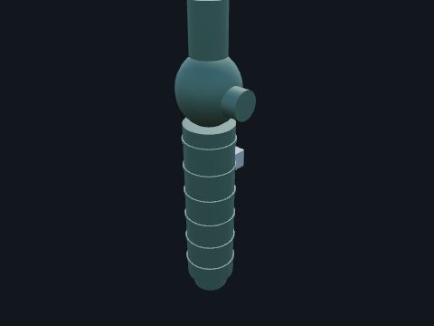
A sealless, canned-motor centrifugal pump mounted upside down on the steam generator channel head, motor below the pump. Circulates reactor coolant through the core and steam generators. The motor rotor runs in reactor coolant inside a sealed can, so there are no shaft seals to leak.
| This plant | Four pumps, about 78,750 gpm at 365 ft head, 7,300 hp, variable-speed drive for startup (model value) |
Safety. Radioactive and at reactor pressure; the motor terminal box is energized.
Standards: ASME BPVC Section III, Division 1, Subsection NB (Class 1), named only, 10 CFR 50.55a (codes and standards), 10 CFR 50 Appendix A, GDC 14 (reactor coolant pressure boundary)
Show it in 3D: Containment × 4Plant site × 4
Fuel assemblies standing in a lattice inside the core barrel, shown here as simple blocks. Fission in the uranium dioxide fuel heats the water flowing up through the assemblies.
| This plant | 157 assemblies, 17 × 17 lattice, 264 fuel rods each, 14 ft active length, about 3,400 MWt (model value) |
| Reactivity | Control rods and boron dissolved in the coolant |
Safety. Irradiated fuel out of water gives a lethal dose rate. During refueling the cavity is flooded and fuel moves only under water.
Standards: 10 CFR 50 Appendix A, GDC 10 (reactor design), 10 CFR 50.46 (ECCS acceptance criteria)
Show it in 3D: Containment × 1Plant site × 1
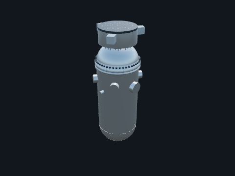
A thick low-alloy steel vessel, stainless clad inside, with outlet, inlet and direct vessel injection nozzles near the top and a bolted closure head. Holds the core and directs coolant down the outside of the core barrel (the downcomer) and up through the fuel.
| This plant | 159 in ID, 8 in beltline wall, about 40 ft tall with the head (model value) |
| Design | 2,485 psig, 650 °F class (model value) |
| Code | ASME BPVC Section III, Division 1, Subsection NB (Class 1): named only; 10 CFR 50 Appendices G and H (fracture toughness, surveillance) |
Safety. The most radioactive component in the plant. Never approach the vessel area without a radiation work permit and the survey map.
Standards: ASME BPVC Section III, Division 1, Subsection NB (Class 1), named only, 10 CFR 50.55a (codes and standards), 10 CFR 50 Appendix A, GDC 14 (reactor coolant pressure boundary), 10 CFR 50 Appendix G (fracture toughness) and Appendix H (vessel surveillance)
Show it in 3D: Containment × 1Plant site × 1
The domed top of the vessel, bolted to the flange with large studs. Removed at every refueling to reach the fuel.
| This plant | 45 studs, 7 in diameter (model value) |
Safety. Highly contaminated on the inside when removed.
Standards: ASME BPVC Section III, Division 1, Subsection NB (Class 1), named only, 10 CFR 50.55a (codes and standards)
Show it in 3D: Containment × 1Plant site × 1
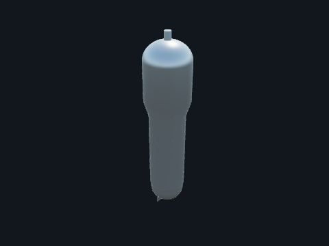
A vertical U-tube heat exchanger about 74 ft tall: reactor coolant enters the channel head, passes through thousands of tubes, and leaves through the pump suctions; feedwater boils on the outside of the tubes. Makes the steam that drives the turbine while keeping the radioactive reactor coolant separate from the turbine cycle.
| This plant | 10,025 tubes, 0.688 in OD Alloy 690; 123,540 ft² of surface; 836 psia, 7.49 × 10⁶ lb/h steam each (model value) |
| Tube integrity | Regulatory Guide 1.121 (tube plugging bases) |
Safety. Primary side radioactive; secondary side at steam pressure.
Standards: ASME BPVC Section III, Division 1, Subsection NB (Class 1), named only, 10 CFR 50.55a (codes and standards), 10 CFR 50 Appendix A, GDC 14 (reactor coolant pressure boundary), Regulatory Guide 1.121 (tube plugging bases)
Show it in 3D: Containment × 2Plant site × 2
Thousands of U-shaped tubes held by support plates. The heat-transfer surface between reactor coolant and feedwater.
| Shown | Representative tubes only |
Standards: Regulatory Guide 1.121 (tube plugging bases)
Show it in 3D: Containment × 2Plant site × 2

A thick plate the tubes pass through, and the plate that divides the channel head into hot and cold sides. Separates reactor coolant from the secondary water and turns the flow.
| This plant | 31 in thick (model value) |
Standards: ASME BPVC Section III, Division 1, Subsection NB (Class 1), named only, 10 CFR 50.55a (codes and standards)
Show it in 3D: Containment × 2Plant site × 2
A spherical tank of borated water pressurized with nitrogen. When reactor pressure falls below the nitrogen pressure, check valves open by themselves and the tank injects a large flow quickly. No signal and no power needed.
| This plant | Two tanks, about 2,000 ft³, nitrogen at about 700 psig (model value) |
Safety. Stored energy: water and gas under high pressure.
Standards: 10 CFR 50.46 (ECCS acceptance criteria), 10 CFR 50 Appendix A, GDC 35 (emergency core cooling), NUREG-0800 SRP 6.3 (emergency core cooling system)
Show it in 3D: Containment × 2Plant site × 2

Steel panels in the annulus between the shield building and the containment vessel. Separates the downward cold-air path (outside the baffle) from the upward warm-air path along the vessel wall, so the air keeps circulating by natural draft.
| This plant | Gap at the bottom where the air turns (model value) |
Safety. The annulus is a confined space.
Standards: 10 CFR 50 Appendix A, GDC 38 (containment heat removal)
Show it in 3D: Containment × 1Plant site × 1
The central opening through the water tank, with a weather hood on top. Warm air that has risen past the containment vessel leaves the shield building here, drawing fresh air in at the inlets.
| This plant | About 49 ft (15 m) across inside the tank (model value) |
Standards: 10 CFR 50 Appendix A, GDC 38 (containment heat removal)
Show it in 3D: Containment × 1Plant site × 1
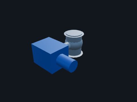
Motor-operated valves in series in the depressurization lines, opened in stages. Lower reactor pressure in steps (stages 1 to 3 to the IRWST spargers, stage 4 into the loop compartments). The core makeup tanks inject at full pressure; as pressure falls the accumulators inject, and at low pressure the IRWST drains in by gravity.
| This plant | Stages 1 to 3: two valve modules over the pressurizer, 4 in and 8 in valves, DC powered (model value) |
Safety. Opens on a depressurization signal; discharge is steam and radioactive water.
Standards: ASME BPVC Section III (valves), named only, ASME OM Code (inservice testing), named only, 10 CFR 50.55a
Show it in 3D: Containment × 16Plant site × 16
Stainless screen modules on the lowest containment floor, behind a curb. Long-term cooling: water that collects in containment flows back into the vessel through these screens; the curb and screens keep debris out.
| This plant | Two screens behind a 2 ft curb (model value) |
Standards: 10 CFR 50.46 (ECCS acceptance criteria), 10 CFR 50 Appendix A, GDC 35 (emergency core cooling)
Show it in 3D: Containment × 1Plant site × 1
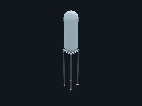
A tall tank of cold, borated water kept at reactor pressure, above the reactor coolant loops. When its discharge valves open, hot coolant enters the top through the balance line and the heavier cold borated water drains into the vessel by gravity: high-pressure makeup with no pumps.
| This plant | Two tanks, about 2,500 ft³ each (model value) |
| Basis | 10 CFR 50.46 (ECCS acceptance criteria) |
Safety. At reactor pressure; radioactive.
Standards: 10 CFR 50.46 (ECCS acceptance criteria), 10 CFR 50 Appendix A, GDC 35 (emergency core cooling), NUREG-0800 SRP 6.3 (emergency core cooling system)
Show it in 3D: Containment × 2Plant site × 2
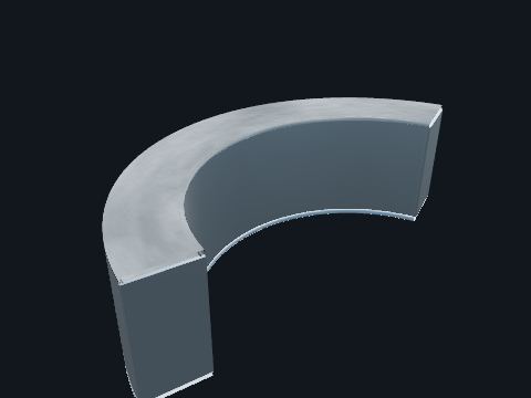
A large stainless-lined tank built into the containment structures, under the operating deck. Holds borated water for gravity injection into the vessel after depressurization, is the heat sink for the passive RHR heat exchanger and the depressurization spargers, and supplies the water that floods the refueling cavity.
| This plant | About 550,000 gal, floor at El. 103 ft (model value) |
| Basis | 10 CFR 50.46 and Appendix A, GDC 35 (emergency core cooling) |
Safety. Large pool of radioactive, borated water; confined space when drained.
Standards: 10 CFR 50.46 (ECCS acceptance criteria), 10 CFR 50 Appendix A, GDC 35 (emergency core cooling), NUREG-0800 SRP 6.3 (emergency core cooling system), 10 CFR 50 Appendix A, GDC 34 (residual heat removal)
Show it in 3D: Containment × 1Plant site × 1
Stainless perforated-plate screen enclosures over the IRWST injection line inlets, against the tank wall. Keep debris out of the injection lines: all water entering a line passes through the screen first.
| This plant | Two shown, one at each injection inlet (model value) |
Standards: 10 CFR 50.46 (ECCS acceptance criteria), 10 CFR 50 Appendix A, GDC 35 (emergency core cooling)
Show it in 3D: Containment × 1Plant site × 1
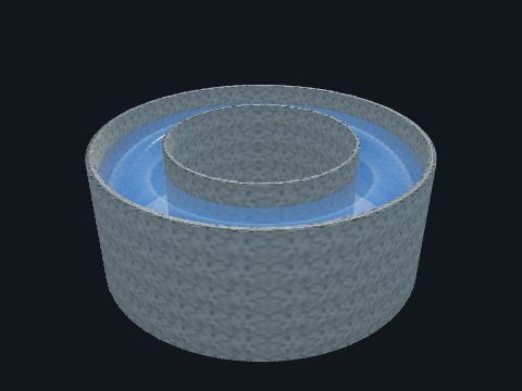
An annular, stainless-lined concrete tank on the shield building roof. After an accident, valves open and the water drains by gravity onto the containment dome for about 72 hours (model value). Evaporation off the hot steel carries heat away. No pumps and no AC power.
| This plant | About 756,700 gal usable, level about 27 ft (model value) |
| Basis | 10 CFR 50 Appendix A, GDC 38 (containment heat removal) |
Safety. Deep water and a roof edge: drowning and fall hazards. Entry is a confined-space and roof-access job.
Standards: 10 CFR 50 Appendix A, GDC 38 (containment heat removal), ACI 349 (nuclear safety-related concrete structures), named only
Show it in 3D: Containment × 1Plant site × 1
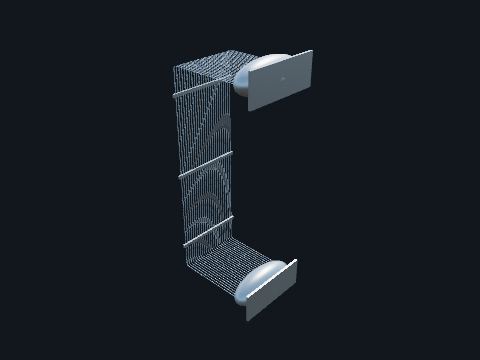
A C-tube heat exchanger hanging in the IRWST, its channel heads attached to the tank wall. Takes decay heat out of the reactor coolant with no pumps: the inlet line from a hot leg is always open, the outlet valves open on a signal, and natural circulation carries hot water up through the tubes and back to the steam generator channel head.
| This plant | 3/4 in Alloy 690 tubes; about 1.78 × 10⁸ Btu/h (52 MW) at 520 °F hot leg and 80 °F tank water (model value) |
| Basis | 10 CFR 50 Appendix A, GDC 34 (residual heat removal) |
Safety. At reactor coolant pressure; radioactive.
Standards: 10 CFR 50 Appendix A, GDC 34 (residual heat removal), ASME BPVC Section III, Division 1, Subsection NB (Class 1), named only
Show it in 3D: Containment × 1Plant site × 1
Stainless steel baskets with mesh fronts, on stands on the lowest containment floor, filled with trisodium phosphate. After an accident the lower containment floods; the trisodium phosphate dissolves and raises the pH of the water that recirculates through the core, which keeps iodine in solution and limits corrosion.
| This plant | At least 26,460 lb of trisodium phosphate, baskets at least a foot above the floor and below the post-accident flood level (NRC HRTD Section 4.0); four baskets shown, number and size are model values |
Safety. Chemical dust when baskets are filled or inspected; follow the chemical handling procedure.
Standards: NRC HRTD Section 4.0, Passive Core Cooling System: trisodium phosphate baskets, quantity and placement, 10 CFR 50.46 (ECCS acceptance criteria)
Show it in 3D: Containment × 1Plant site × 1
A pipe hub with perforated arms near the bottom of the IRWST. Spreads depressurization steam into the water so it condenses quietly instead of in large bubbles.
Standards: 10 CFR 50.46 (ECCS acceptance criteria), 10 CFR 50 Appendix A, GDC 35 (emergency core cooling)
Show it in 3D: Containment × 2Plant site × 2
A slotted bucket at the dome crown and radial weirs on the dome. Spreads the cooling water into an even film over the dome and down the vessel wall.
Standards: 10 CFR 50 Appendix A, GDC 38 (containment heat removal)
Show it in 3D: Containment × 1Plant site × 1
Concrete floors inside containment: the operating deck, with openings over the steam generators, pressurizer, core makeup tanks and the refueling cavity, and the maintenance floor on the east side at the lower hatch and airlock. Working floors for refueling, crane lifts and outage maintenance, and access to the lower equipment hatch and personnel airlock.
| This plant | Operating deck at El. 140 ft; maintenance floor at El. 107 ft 2 in on concrete columns and fill (model values) |
| Walking surfaces | Guardrails at open edges and floor openings: OSHA 29 CFR 1910.28(b)(1) and (b)(3), 1910.29(b) |
Safety. Open edges and floor openings: falls. Heavy loads overhead from the polar crane.
Standards: ACI 349 (nuclear safety-related concrete structures), named only, AISC N690 (nuclear steel structures), named only, Regulatory Guide 1.29 (seismic design classification)
Show it in 3D: Containment × 2Plant site × 2
Concrete and steel-concrete composite modules inside the containment vessel. Support the reactor coolant system, shield the reactor (the primary shield wall around the cavity), and form the compartments, the refueling cavity and the IRWST.
| This plant | Loop compartment floor shown at plant El. 83 ft (model value) |
Standards: ACI 349 (nuclear safety-related concrete structures), named only, AISC N690 (nuclear steel structures), named only, Regulatory Guide 1.29 (seismic design classification)
Show it in 3D: Containment × 4Plant site × 4
A sealed canister through the containment wall carrying cables through header plates. Gets power, control and instrument cables in and out without breaking the containment boundary. Divisions use separate penetrations.
| Shown | Generic canister type; one group for each Class 1E division (A to D, Division A in two groups) and one for non-safety power (model value) |
| Standard | IEEE 317 (electrical penetration assemblies): named only |
Standards: IEEE 317 (electrical penetration assemblies), named only, 10 CFR 50 Appendix J, 10 CFR 50.49
Show it in 3D: Containment × 6Plant site × 6
A large bolted opening through the containment vessel with a pressure-seated cover. Lets large equipment in and out during outages; closed and sealed whenever containment integrity is required. Both hatches open into the auxiliary building, through openings in the shield building wall.
| This plant | Two hatches, 16 ft inside diameter (model value) |
| Testing | 10 CFR 50 Appendix J |
Standards: ASME BPVC Section III, Subsection NE, named only, 10 CFR 50 Appendix J
Show it in 3D: Containment × 2Plant site × 2
A stainless tube in a sleeve through the containment wall, between the refueling cavity and the fuel handling area. During refueling, fuel assemblies pass through it on a carriage between containment and the spent fuel area. A blind flange closes the containment end during operation.
| This plant | 24 in sleeve (model value) |
| Testing | 10 CFR 50 Appendix J (the blind flange is part of the containment boundary) |
Safety. Radioactive water and irradiated fuel pass through it during refueling.
Standards: 10 CFR 50 Appendix J (containment leak testing: the blind flange is part of the containment boundary), ASME Section III, Subsection NE (metal containment), named only
Show it in 3D: Containment × 2Plant site × 2
A short steel chamber through the containment wall with two interlocked doors. People enter and leave containment while one door always stays shut.
| This plant | Two airlocks, about 10 ft OD (model value) |
Standards: ASME BPVC Section III, Subsection NE, named only, 10 CFR 50 Appendix J
Show it in 3D: Containment × 2Plant site × 2
A stainless-lined concrete pit above the reactor vessel. Flooded during refueling, so the head, internals and fuel move under water, which shields the radiation.
| This plant | 4 ft concrete walls with stainless liner (model value) |
Safety. Fall hazard at the edge, and radioactive water when flooded. Foreign material exclusion applies.
Standards: ACI 349 (nuclear safety-related concrete structures), named only, AISC N690 (nuclear steel structures), named only, Regulatory Guide 1.29 (seismic design classification)
Show it in 3D: Containment × 1Plant site × 1
A gantry bridge on rails along the refueling cavity, with a trolley and a telescoping mast that grips one fuel assembly at a time. Moves fuel assemblies under water between the core and the fuel transfer system during refueling outages.
| This plant | Arrangement is a model value |
| Heavy loads | NUREG-0612 (control of heavy loads) |
Safety. Moving machinery over an open, flooded cavity; hoist travel is limited so fuel stays under water (typical).
Standards: NUREG-0612 (control of heavy loads), ANS-57.1 (light water reactor fuel handling systems), named only
Show it in 3D: Containment × 1Plant site × 1
A reinforced concrete cylinder, steel-concrete composite where it is exposed, around the steel containment vessel, with air inlets near the top, a conical roof, a water tank and a central air outlet. Protects the containment from outside hazards (wind, missiles, earthquakes), shields radiation, and is the chimney for passive containment cooling: air enters at the top, flows down outside the baffle, turns, and rises past the hot vessel.
| This plant | 145 ft OD, 3 ft wall; top of the cooling water tank about 229 ft above grade, with the air outlet hood above it (model value) |
| Codes | 10 CFR 50 Appendix A, GDC 2 (natural phenomena); seismic Category I (Regulatory Guide 1.29 Rev. 6) |
Safety. Confined spaces in the annulus and roof areas; falls from roof edges.
Standards: 10 CFR 50 Appendix A, GDC 2 (natural phenomena), ACI 349 (nuclear safety-related concrete structures), named only, AISC N690 (nuclear steel structures), named only, Regulatory Guide 1.29 (seismic design classification)
Show it in 3D: Containment × 1Plant site × 1
A free-standing steel pressure vessel, 130 ft across and about 215 ft tall (model values), with ellipsoidal heads; its bottom head is embedded in concrete. The containment pressure boundary: after an accident it holds the steam and radioactive material in. Its outside surface also carries heat to the cooling air and water film, which is how passive containment cooling works.
| This plant | SA-738 Gr B steel, 1.75 in cylinder, 1.625 in heads, design 59 psig at 300 °F, about 2.06 × 10⁶ ft³ free volume (model value) |
| Testing | Leak-rate tested under 10 CFR 50 Appendix J |
| Code | ASME BPVC Section III, Division 1, Subsection NE (Class MC): named only |
Safety. Inside: radiation, heat stress and confined spaces during outages. Entry only through the airlocks on a radiation work permit.
Standards: ASME BPVC Section III, Division 1, Subsection NE (Class MC), named only, 10 CFR 50 Appendix J (leak-rate testing), 10 CFR 50 Appendix A, GDC 16 and 50 (containment design)
Show it in 3D: Containment × 1Plant site × 1

Water inside a tank or vessel, drawn translucent so the cutaway shows the level. Shows where the water sits: in the cooling water tank, the IRWST and the pressurizer.
Safety. Water from the reactor coolant system and the IRWST is radioactive and borated.
Show it in 3D: Containment × 3Plant site × 3
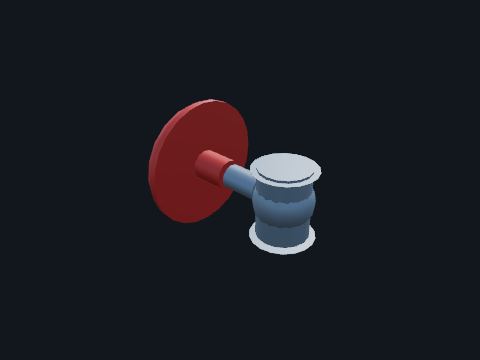
A valve moved by an air diaphragm actuator, with a spring that drives it to its safe position. In the passive systems these valves fail open: losing air or power lets the spring open them. The pressurizer spray valve is the opposite: it fails closed.
| Shown | Core makeup tank discharge, passive RHR outlet and cooling water drain valves (fail open); pressurizer spray valve (fails closed) (model value) |
Safety. Can move suddenly when air or a signal changes.
Standards: ASME BPVC Section III (valves), named only, ASME OM Code (inservice testing), named only, 10 CFR 50.55a
Show it in 3D: Containment × 6Plant site × 6
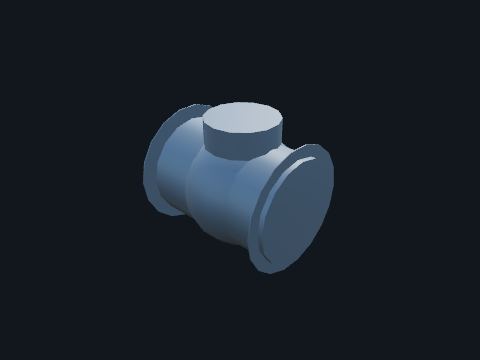
A valve that lets flow pass one way only. Opens on forward flow (injection toward the vessel) and closes against reverse flow.
Standards: ASME BPVC Section III (valves), named only, ASME OM Code (inservice testing), named only, 10 CFR 50.55a
Show it in 3D: Containment × 6Plant site × 6
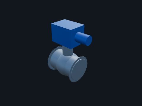
A valve driven by an electric motor actuator. Shown on the passive RHR inlet (normally open) and in the cooling water drain paths from the roof tank.
Safety. Can operate remotely.
Standards: ASME BPVC Section III (valves), named only, ASME OM Code (inservice testing), named only, 10 CFR 50.55a
Show it in 3D: Turbine building × 3Containment × 5Plant site × 8
Stainless steel pipe connecting the passive tanks, heat exchanger and depressurization valves to the reactor coolant system. Direct vessel injection, core makeup tank balance and discharge, passive RHR, automatic depressurization lines, and the cooling water drain from the roof tank to the dome.
| Sizes | NPS 4 to 18, Sch 160 (model value); outside diameters from free published pipe charts that list the ASME B36.19M sizes (the standard is named only) |
| Cooling water drain | Three parallel NPS 8 Sch 40S paths (model value) |
Safety. Treat every line as pressurized and hot until a clearance says otherwise.
Standards: ASME BPVC Section III (Class 1 and 2 piping), named only, ASME B36.19M (stainless pipe sizes), named only, 10 CFR 50.55a
Show it in 3D: Containment × 41Plant site × 41
Clamps, struts and posts that hold piping. Carry weight and limit movement.
Show it in 3D: Turbine building × 116Containment × 9Plant site × 125
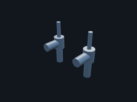
Spring-loaded safety valves on top of the pressurizer. Open automatically if pressure gets too high, protecting the reactor coolant pressure boundary.
| This plant | Two, 6 in inlet × 8 in outlet (model value) |
Safety. Can open without warning; discharge is hot and radioactive.
Standards: ASME BPVC Section III, Division 1, Subsection NB (Class 1), named only, 10 CFR 50.55a (codes and standards), 10 CFR 50 Appendix A, GDC 15
Show it in 3D: Containment × 1Plant site × 1
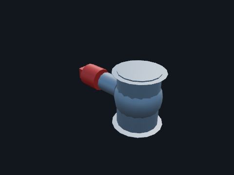
A valve opened by a small explosive charge that drives a piston. Opens once, fully and fast, and stays open: used for the final depressurization stage and the IRWST injection lines.
| Testing | Inservice testing under the ASME OM Code: named only |
Safety. Contains an explosive actuator. Work on it only under its procedure.
Standards: ASME BPVC Section III (valves), named only, ASME OM Code (inservice testing), named only, 10 CFR 50.55a
Show it in 3D: Containment × 6Plant site × 6
A small chamber at the top of a reference leg. Keeps the reference leg full of water so the level measurement stays correct.
Standards: Regulatory Guide 1.151 Rev. 2
Show it in 3D: Containment × 1Plant site × 1

An electronic transmitter that measures the difference between two pressures, mounted on a stand and connected to the process by tubing. Here it measures pressurizer level: the difference between the water column in the vessel and a reference leg kept full of water.
| Signal | 4–20 mA to the protection system cabinets |
| Qualification | 10 CFR 50.49 (environmental qualification) |
Safety. The tubing and manifold are at full process pressure.
Standards: 10 CFR 50.49 (environmental qualification), IEEE 603 (criteria for safety systems), named only, Regulatory Guide 1.151 Rev. 2 (instrument sensing lines)
Show it in 3D: Turbine building × 2Containment × 1Plant site × 3
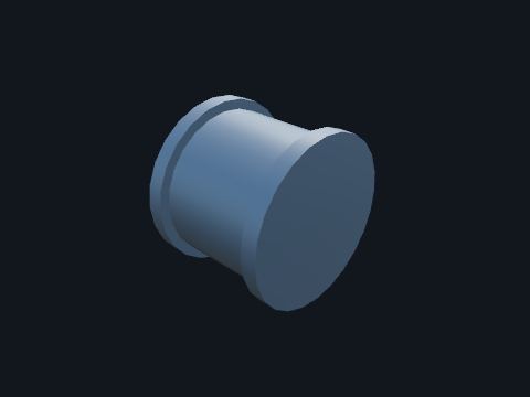
A shaped restriction in the pipe with pressure taps upstream and at the throat. Makes a pressure drop that a differential pressure transmitter turns into a flow signal: flow goes as the square root of the pressure drop.
Standards: ASME MFC-3M (flow measurement with differential pressure devices), named only
Show it in 3D: Turbine building × 2Plant site × 2

A 2 in pipe stand on a base plate with a transmitter bracket. Holds a remote-mounted transmitter where it can be reached and kept below its process taps.
Standards: Regulatory Guide 1.151 Rev. 2
Show it in 3D: Turbine building × 5Containment × 2Plant site × 7
Small stainless tubing between a process tap and a transmitter. Carries the process pressure to the transmitter. Liquid lines slope down toward the transmitter so gas cannot collect.
| This plant | 1/2 in OD × 0.065 in wall 316 stainless (catalog working pressure about 5,100 psig, seamless, room temperature) |
| Guide | Regulatory Guide 1.151 Rev. 2 (instrument sensing lines; endorses ISA-67.02.01-2014) |
Safety. Do not step on it or use it as a handhold: a broken line sprays reactor coolant.
Standards: Regulatory Guide 1.151 Rev. 2 (endorses ISA-67.02.01-2014), ASTM A269 (stainless tubing), named only
Show it in 3D: Turbine building × 7Containment × 4Plant site × 11
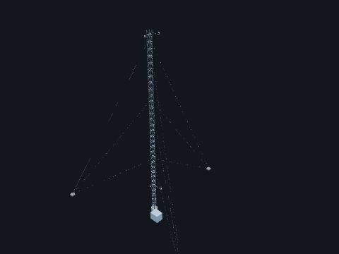
A guyed open-lattice tower about 60 m tall with wind instruments on booms near the bottom and the top. Measures wind speed and direction at about 10 m and 60 m and the temperature difference between the two levels. The data feed routine release dispersion estimates and emergency dose projections.
| Basis | Regulatory Guide 1.23 Rev. 1, Meteorological Monitoring Programs for Nuclear Power Plants: wind at about 10 m and 60 m on one open-lattice tower or mast, temperature difference between the 10 m and 60 m levels |
| Size | Tower height follows the guide; guys and shelter are model values |
Safety. Climbing a tower is work at height: fall protection, and stay clear of the guy anchors.
Standards: Regulatory Guide 1.23 Rev. 1 (meteorological monitoring programs)
Show it in 3D: Plant site × 1

An electronic transmitter that measures process pressure through a sensing line. Here it measures pressurizer (reactor coolant) pressure for control and protection.
| Signal | 4–20 mA |
Safety. At full process pressure.
Standards: 10 CFR 50.49 (environmental qualification), IEEE 603 (criteria for safety systems), named only, Regulatory Guide 1.151 Rev. 2 (instrument sensing lines)
Show it in 3D: Turbine building × 3Containment × 1Plant site × 4

The first isolation valve at a process tap. Isolates the instrument line from the process.
Standards: ASME BPVC Section III (valves), named only
Show it in 3D: Turbine building × 7Containment × 3Plant site × 10
A concrete outfall on the riverbank. Returns a small flow of tower water (blowdown) to the river, which keeps dissolved solids in the tower down. Discharge limits come from the plant's water permit.
| Size | Model value |
Standards: 40 CFR Part 122 (NPDES permits)
Show it in 3D: Plant site × 1
A concrete wet pit beside the tower basin with vertical pump motors on top. Pumps cooled water from the basin back through the condenser.
| This plant | Three 33-1/3% vertical, wet-pit, mixed-flow, motor-driven pumps (public plant description); about 600,000 gpm in all (model value, from a public utility study) |
Safety. Deep water and pits below the deck; motors start automatically.
Standards: NUREG-0800 SRP 10.4.5, Hydraulic Institute intake design standard, named only
Show it in 3D: Plant site × 1
Horizontal double-wall tanks next to the diesel building. Store fuel for the standby diesels.
| Size | Model value |
Safety. Combustible liquid; no ignition sources.
Standards: NFPA 30 (flammable and combustible liquids), named only, 40 CFR 112 (spill prevention, control and countermeasure)
Show it in 3D: Plant site × 1
A concrete pad with a hydrogen tube bank and a carbon dioxide tank, away from buildings. Hydrogen fills and makes up the hydrogen-cooled generator. Carbon dioxide purges the generator casing before hydrogen goes in and after it comes out, so air and hydrogen never mix.
| Siting | Gaseous hydrogen systems are located per OSHA 29 CFR 1910.103(b)(2); the spacing shown is a model value |
| Size | Model value |
Safety. Hydrogen is flammable over a wide range and burns with an almost invisible flame. No ignition sources; carbon dioxide displaces oxygen in low areas.
Standards: OSHA 29 CFR 1910.103 (hydrogen), NFPA 55 (compressed gases and cryogenic fluids), named only
Show it in 3D: Plant site × 1
A hyperbolic reinforced concrete shell standing on diagonal columns over a water basin. Cools the circulating water: warm water from the condenser falls through the fill, air drawn in at the base by the chimney effect cools it, and a small part evaporates. The cooled water collects in the basin and goes back to the condenser. The plume is water vapor.
| This plant | One natural draft tower (public plant description); about 600 ft tall and 400 ft across at the base (secondary public sources; model value) |
| Makeup | Raw water replaces evaporation, drift and blowdown (public plant description) |
Safety. Basin, shell and fill: drowning, falls and confined spaces. Ice and fog near the tower in cold weather.
Standards: NUREG-0800 SRP 10.4.5 (circulating water system), ACI 334.2R (reinforced concrete cooling tower shells), named only
Show it in 3D: Plant site × 1
A vertical steel tank on a ring foundation. Stores water for the plant: condensate, demineralized makeup water, fire protection water, and the ancillary water that refills the passive containment cooling tank after the first three days of an accident.
| This plant | Ancillary passive containment cooling water at least 780,000 gal (public plant description); other volumes are model values |
Safety. Tank entry is a permit-required confined space [OSHA 29 CFR 1910.146]; roofs are fall hazards.
Standards: AWWA D100 (welded steel water tanks), named only, NFPA 22 (water tanks for fire protection), named only
Show it in 3D: Plant site × 5
A bridge crane running on a circular rail near the top of the containment vessel. Lifts the reactor head, internals, pump motors and other heavy loads during outages.
| This plant | 300 t main hook, 25 t auxiliary (model value) |
| Heavy loads | NUREG-0612 (control of heavy loads) |
Safety. Never stand under a suspended load.
Standards: NUREG-0612 (control of heavy loads), ASME NOG-1 (overhead and gantry cranes, nuclear), named only
Show it in 3D: Containment × 1Plant site × 1
A concrete intake on the riverbank with trash racks, screens and makeup pumps. Draws raw water from the river to make up what the cooling tower loses.
| Size | Model value |
| Intake rule | A new plant drawing 10 million gallons a day or more that follows Track I must cut its intake flow to what a closed-cycle recirculating system needs and keep the through-screen design intake velocity at or below 0.5 ft/s (40 CFR 125.84(b)) |
Safety. Moving water and pits: fall protection and a life jacket near open water.
Standards: 40 CFR Part 125 (Clean Water Act section 316(b) cooling water intakes)
Show it in 3D: Plant site × 1
A two-cell mechanical draft cooling tower next to the turbine building, with louvered air inlets and a fan stack on each cell. Cools the non-safety service water system, which carries heat away from the component cooling water heat exchangers. Each cell has its own fan and can run on its own.
| This plant | Two cells, each able to run on its own; next to the turbine building; non-safety (public plant description); size is a model value |
Safety. Rotating fans, wet slippery decks and the basin. Lock out the fan before entering a cell.
Standards: NUREG-0800 SRP 9.2.1 (station service water system)
Show it in 3D: Plant site × 1
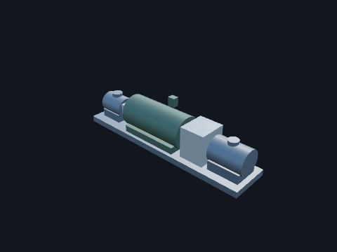
A booster pump and a main feedwater pump driven from the two ends of one motor, the main pump through a speed increaser. Raises feedwater to steam generator pressure; the main feedwater control valves set the flow to each steam generator.
| This plant | Three pump sets running in parallel; separate startup feedwater pumps are used for startup; the main feedwater control valves hold steam generator level (public plant description); motor rating and sizes are model values |
Safety. Large medium-voltage motors, high-pressure water and couplings.
Standards: NUREG-0800 SRP 10.4.7, Hydraulic Institute pump standards, named only
Show it in 3D: Turbine building × 3Plant site × 3
Large buried pipes between the cooling tower and the condenser, plus the river makeup and blowdown lines. Carry cooling water to the condenser and back to the tower.
| This plant | Buried piping is concrete pressure pipe (public plant description); sizes are model values |
| Flow | About 600,000 gpm (model value, from a public utility study for this type of plant) |
Safety. Buried: excavation near it is a planned, permitted job.
Standards: NUREG-0800 SRP 10.4.5 (circulating water system), AWWA C301 / C303 (concrete pressure pipe), named only
Show it in 3D: Turbine building × 4Plant site × 6

Slip rings on the end of the generator shaft and the carbon brushes that ride on them. Carry DC field current from the static excitation system into the spinning rotor winding.
| This plant | Static excitation through a thyristor full-bridge rectifier, fed by an excitation transformer outdoors next to the turbine building (public plant description) |
Safety. Energized at field voltage whenever the generator is excited. Brush work on a running machine follows its own procedure.
Standards: IEEE 421.1 (excitation system definitions), named only
Show it in 3D: Turbine building × 1Plant site × 1
Carbon steel piping from the hotwell through the heaters to the deaerator, from the feedwater pumps through the HP heaters to the steam generators, and the heater drain lines. Carries the water side of the cycle back to the steam generators.
| Heater drains | HP heater drains cascade to the deaerator; each LP heater drains to the next lower heater, and heater 1 drains to its condenser shell (public plant description) |
| Sizes | Model values; the feedwater side is insulated |
Safety. Feedwater runs hot and at high pressure: a leak flashes to steam.
Standards: NUREG-0800 SRP 10.4.7 (condensate and feedwater system), ASME B31.1 (power piping), named only
Show it in 3D: Turbine building × 41Plant site × 43
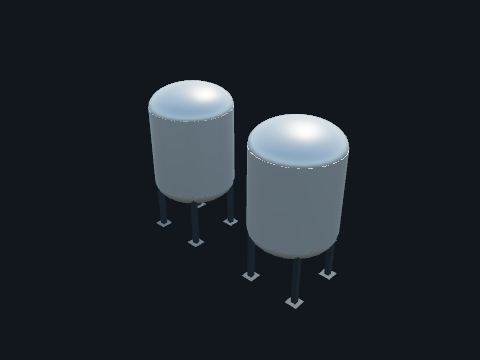
Large vessels filled with mixed ion exchange resin, piped as a sidestream off the condensate header between the condensate pumps and the LP heaters. Cleans the condensate: the resin takes out dissolved salts and corrosion products, for example after a condenser tube leak or during startup. It is normally bypassed at power.
| This plant | Deep-bed mixed-resin demineralizer for about one-third of the maximum condensate flow; used at startup and hot standby, and at power only when secondary water chemistry is off normal (public plant description); two vessels and their sizes are model values |
| Valves | Inlet and outlet isolation valves normally closed, the header valve between the two tees normally open (model value) |
Safety. Resin vessels hold condensate under pump pressure; resin transfer and regeneration chemicals are handled under their own procedures.
Standards: NUREG-0800 SRP 10.4.6 (condensate cleanup system), NRC HRTD 7.2, Condensate and Feedwater System
Show it in 3D: Turbine building × 1Plant site × 1
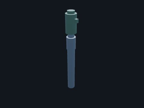
A vertical multistage can pump: the pump hangs in a can below the floor and the motor sits on top. Takes water from the condenser hotwell and pushes it through the LP heaters to the deaerator.
| This plant | Three 50% pumps; two carry full power (public plant description) |
Safety. Rotating equipment that starts automatically; the suction side is under vacuum.
Standards: NUREG-0800 SRP 10.4.7, Hydraulic Institute pump standards, named only
Show it in 3D: Turbine building × 3Plant site × 3
Pipes from each condenser shell to the vacuum pumps, and the vent from the pump separators to the outside. Carry the air and gases the vacuum pumps remove.
| Sizes | Model values |
Standards: ASME B31.1 (power piping), named only
Show it in 3D: Turbine building × 14Plant site × 14
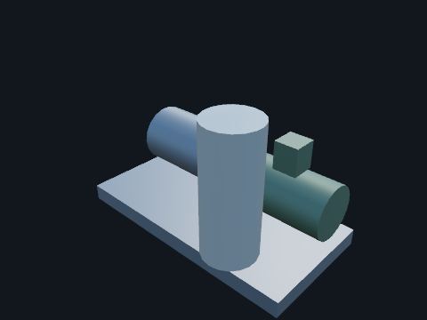
A liquid ring vacuum pump with its separator tank and motor on one skid. Pulls air and other gases that leak into the condenser out, so the vacuum holds.
| This plant | Four pumps: one per shell plus a standby (public plant description) |
Safety. Starts automatically.
Standards: NUREG-0800 SRP 10.4.2 (main condenser evacuation system)
Show it in 3D: Turbine building × 4Plant site × 4
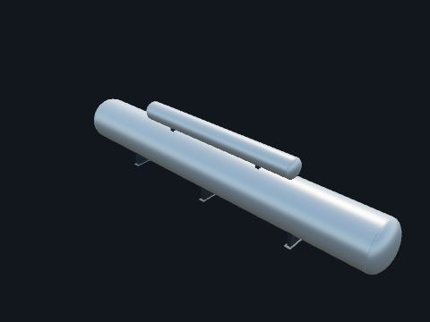
An open heater on top of a large storage tank, high in the heater bay. Mixes the condensate with steam to drive out dissolved gases and heat it, then stores it for the feedwater pumps. Its height gives the booster pumps the suction head they need.
| This plant | The fifth heater stage, fed from the HP turbine exhaust (public plant description); size is a model value |
Safety. A large volume of hot water near boiling: a leak flashes to steam.
Standards: ASME BPVC Section VIII, Division 1, named only, NUREG-0800 SRP 10.4.7
Show it in 3D: Turbine building × 1Plant site × 1
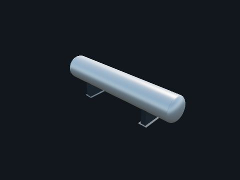
A closed heat exchanger: feedwater in the tubes, steam bled from the turbine in the shell. Preheats the feedwater with extraction steam, which raises the efficiency of the cycle.
| This plant | Seven stages: four closed LP heaters (heaters 1 and 2 are in the condenser necks), the deaerator as the fifth, and two HP stages; HP drains go to the deaerator, LP drains cascade toward the condenser (public plant description) |
| Strings | Heaters 1 and 2: three parallel strings, one in each condenser neck (inside the necks, not drawn); heaters 3 and 4 and heaters 6 and 7: two parallel strings each (public plant description); sizes are model values |
Safety. Isolate both the water side and the steam side before opening a heater.
Standards: HEI Standards for Closed Feedwater Heaters, named only, ASME BPVC Section VIII, Division 1, named only
Show it in 3D: Turbine building × 8Plant site × 8
Supports between the casings that hold the journal bearings. The front standard at the HP end holds the thrust bearing and the trip devices (arrangement is a model value). Carry the rotors on a film of oil and hold their axial position.
| Overspeed | The trip system closes the steam supply valves if speed exceeds 110% of rated (public plant description) |
Safety. Hot lube oil under pressure: an oil leak onto hot steam piping is a turbine hall fire hazard.
Standards: NUREG-0800 SRP 10.2 (turbine generator: overspeed protection)
Show it in 3D: Turbine building × 1Plant site × 1
Skids for the hydrogen seal oil and the stator cooling water. Keep the hydrogen inside the generator at the shaft seals, and pump de-ionized water through the hollow stator bars.
| This plant | Hydrogen at 75 psig; de-ionized water in the stator (public plant description) |
Safety. Hydrogen: no ignition sources near the generator and its gas system without a hot work permit.
Standards: NFPA 804 (fire protection for advanced light water reactor plants), named only
Show it in 3D: Turbine building × 3Plant site × 3
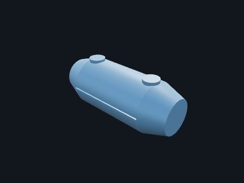
A double-flow steam turbine: main steam enters at the middle of the casing and expands outward through rows of blades in both directions. Turns part of the main steam's energy into shaft power. Its exhaust, now wetter and at lower pressure, goes to the moisture separator reheaters as cold reheat steam.
| This plant | One double-flow HP turbine in a tandem-compound, six-flow, 1,800 rpm unit with three LP turbines (public plant description) |
| Steam | About 821 psig and 523 °F at the steam generator outlets, 7.49 × 10⁶ lb/h from each of two steam generators (public plant description) |
| Code | 10 CFR 50 Appendix A, GDC 4 and Regulatory Guide 1.115 (turbine missiles): named only |
Safety. High-energy steam, hot surfaces and noise. Casings are opened only inside a clearance with the steam valves, drains and the turning gear isolated.
Standards: 10 CFR 50 Appendix A, GDC 4 (environmental and dynamic effects, including missiles), Regulatory Guide 1.115 (protection against turbine missiles), NUREG-0800 SRP 10.2 (turbine generator), ASME PTC 6 (steam turbine performance test code), named only
Show it in 3D: Turbine building × 1Plant site × 1
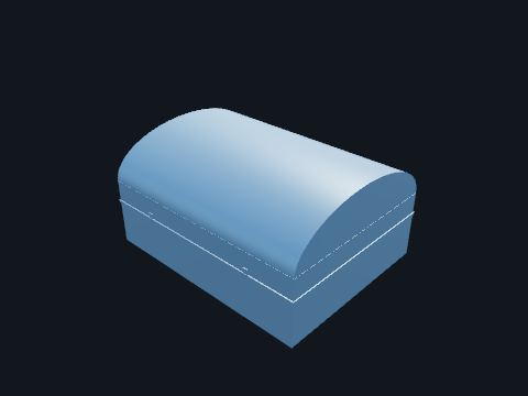
A large double-flow turbine with the longest blades in the machine, exhausting downward into the condenser. Expands the reheated steam all the way down to condenser vacuum. Most of the unit's power is made here.
| This plant | Three double-flow LP turbines with 52 in last-stage blades (public plant description) |
| Exhaust | Condenser design pressure 2.9 in HgA (public plant description) |
Safety. Rotating parts and vacuum: a casing is opened only after the turning gear and oil systems are locked out.
Standards: 10 CFR 50 Appendix A, GDC 4 (environmental and dynamic effects, including missiles), Regulatory Guide 1.115 (protection against turbine missiles), NUREG-0800 SRP 10.2.3 (turbine rotor integrity)
Show it in 3D: Turbine building × 3Plant site × 3
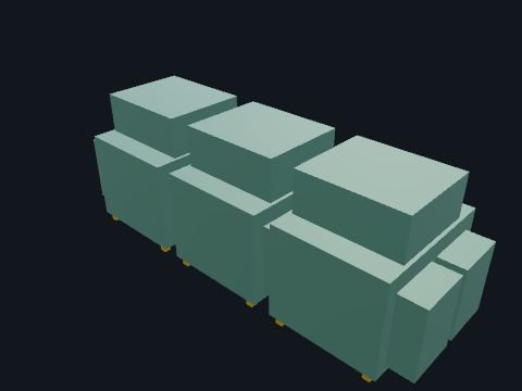
Three large steel shells under the LP turbines, packed with tubes that carry circulating water from the cooling tower. Condenses the turbine exhaust back to water under vacuum. The lower the pressure, the more work the LP turbines can do. The water collects in the hotwell at the bottom.
| This plant | Three shells, single pass, multipressure, spring supported; titanium or stainless steel tubes; two LP feedwater heaters in the neck of each shell (public plant description) |
| Design | 2.9 in HgA; dissolved oxygen kept below 10 ppb at full power; hotwell holds at least three minutes of full-load condensate flow (public plant description) |
| Bypass | Takes up to 40% of full-load steam flow from the turbine bypass valves (public plant description) |
Safety. Opened water boxes and shells are confined spaces, usually permit-required; the plant's evaluation decides [OSHA 29 CFR 1910.146].
Standards: NUREG-0800 SRP 10.4.1 (main condensers), HEI Standards for Steam Surface Condensers, named only
Show it in 3D: Turbine building × 1Plant site × 1
Large insulated pipes: main steam from the steam generators, cold reheat to the moisture separator reheaters, crossovers to the LP turbines, the turbine bypass lines, and the extraction and heating steam lines to the feedwater heaters, the deaerator and the reheaters. Carry steam between the major parts of the cycle.
| Main steam | Two lines; the MSIVs and the twelve 8 × 10 in main steam safety valves are upstream in the auxiliary building; pipe is SA-335 Gr P11 (public plant description) |
| Extraction | HP turbine extraction to HP heaters 6 and 7 and to the first reheat stage, HP turbine exhaust to the deaerator, main steam to the second reheat stage, LP turbine extraction to the LP heaters (public plant description); routing is a model value |
| Sizes | Model values |
Safety. High-energy lines: a break releases steam that can kill. Work on them only inside a clearance that has isolated, drained and vented the line.
Standards: NUREG-0800 SRP 10.3 (main steam supply system), ASME B31.1 (power piping), named only
Show it in 3D: Turbine building × 38Plant site × 40
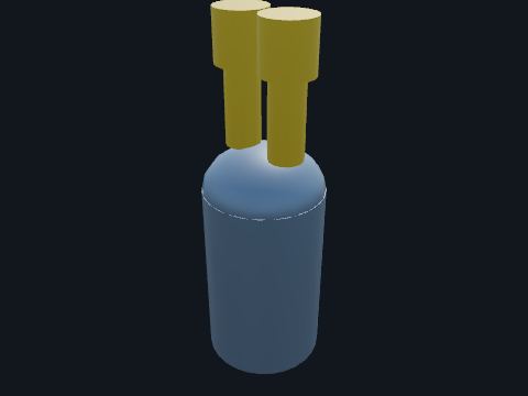
Valve chests beside the HP turbine, each a stop valve in series with a governing control valve, worked by hydraulic actuators. The control valves throttle steam to set the load; the stop valves close fast on a turbine trip.
| This plant | Four stop valves, each in series with one of four control valves (public plant description) |
Safety. They close fast with large stored hydraulic energy: hands off valve linkages unless the actuators are isolated.
Standards: NUREG-0800 SRP 10.2 (turbine generator), Regulatory Guide 1.115
Show it in 3D: Turbine building × 4Plant site × 4
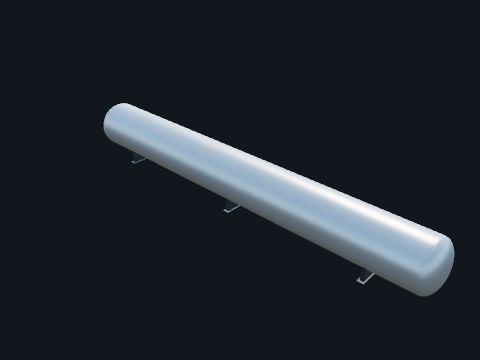
A long horizontal vessel with chevron separators and steam-heated tube bundles inside. Removes the water that forms as steam expands in the HP turbine, then reheats the steam before it enters the LP turbines. Wet steam would erode the LP blades.
| This plant | Two MSRs with two reheat stages: the first heated by HP extraction steam, the second by main steam; separator outlet moisture at most 0.25% (public plant description) |
Safety. Steam and hot drains under pressure.
Standards: ASME BPVC Section VIII, Division 1 (pressure vessels), named only
Show it in 3D: Turbine building × 2Plant site × 2
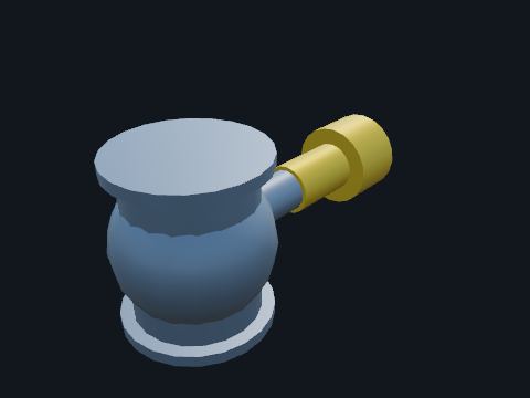
Valves in each crossover pipe between the moisture separator reheaters and the LP turbines. Close on a trip or overspeed so the large volume of steam stored in the reheaters and crossovers cannot drive the turbine faster.
| This plant | Six reheat steam lines, each with a reheat stop valve and an intercept valve (public plant description) |
Safety. Fast-acting hydraulic actuators; work only inside a clearance.
Standards: NUREG-0800 SRP 10.2 (turbine generator), Regulatory Guide 1.115
Show it in 3D: Turbine building × 6Plant site × 6
Thyristor rectifier cubicles, with an AC bus duct in from the excitation transformer and a DC bus duct out to the collector rings. Turns AC from the excitation transformer into the DC field current for the generator rotor, and sets that current to control generator voltage.
| This plant | Static excitation through a thyristor full-bridge rectifier, fed by an excitation transformer outdoors next to the turbine building (public plant description); cubicle and duct sizes are model values |
Safety. Energized at field voltage whenever the generator is excited; the AC side is energized whenever the generator is turning.
Standards: IEEE 421.1 (excitation system definitions), named only
Show it in 3D: Turbine building × 3Plant site × 3
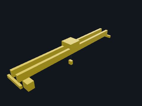
An overhead double-girder bridge crane running the length of the turbine bay. Lifts casings, rotors, valves and generator parts during outages.
| This plant | About 250 t main hook, about 126 ft span (model value) |
Safety. Never stand under a suspended load [OSHA 29 CFR 1910.179].
Standards: OSHA 29 CFR 1910.179 (overhead and gantry cranes), ASME B30.2 (overhead cranes), named only
Show it in 3D: Turbine building × 1Plant site × 1
One of six large globe valves that send main steam straight to the condenser. Open when the turbine cannot take the steam, such as after a load rejection or a turbine trip, and dump it to the condenser. Working with the reactor control systems, this limits the rise in steam pressure.
| This plant | Six 16 in globe valves, up to 998,000 lb/h each; together 40% of full-load steam flow (public plant description) |
Safety. Opens automatically and fast; the downstream line and the condenser inlet get hot.
Standards: NUREG-0800 SRP 10.4.4 (turbine bypass system)
Show it in 3D: Turbine building × 6Plant site × 6

A skid of pumps, accumulators and filters supplying high-pressure, fire-resistant hydraulic fluid. Powers the actuators that open and close the turbine steam valves. The fluid is fire resistant because its lines run to valves next to hot steam piping.
| This plant | Independent of the lube oil (public plant description) |
Safety. High-pressure hydraulic fluid: a pinhole leak can inject fluid through skin.
Show it in 3D: Turbine building × 1Plant site × 1
A reservoir with AC and DC oil pumps, coolers and filters. Supplies cooled oil to every turbine-generator bearing; a DC emergency pump keeps oil flowing while the machine coasts down if AC power is lost.
| This plant | Independent of the turbine control fluid system (public plant description); capacity is a model value |
| Fire | NFPA 804 (fire protection for advanced light water reactor plants): named only; the plant fire protection program follows Regulatory Guide 1.189 |
Safety. A large volume of combustible oil near hot steam piping: leaks and oil-soaked insulation are fire hazards.
Standards: NFPA 804 (fire protection for advanced light water reactor plants), named only, Regulatory Guide 1.189 (fire protection program)
Show it in 3D: Turbine building × 3Plant site × 3
Clothing and hood with a tested arc rating in cal/cm². Protects against burns inside the arc-flash boundary.
Standards: ASTM F1959, NFPA 70E
Reference entry, not built in a building yet
Contact or proximity tester on a hot stick. Tests for absence of voltage before grounds are applied.
Standards: ASTM F1796
Reference entry, not built in a building yet
Fiberglass insulated pole with interchangeable tools. Operates switches and applies grounds from a safe distance.
Standards: ASTM F711, IEEE 978
Reference entry, not built in a building yet
Shepherd's hook on an insulated pole. Pulls a person off an energized source without touching them.
Standards: OSHA 1910.269
Reference entry, not built in a building yet
Rubber covers placed over energized or grounded parts. Cover nearby parts so a worker cannot contact them.
Standards: ASTM D1048, ASTM D1050, ASTM D1051
Reference entry, not built in a building yet
Locks, tags and lock boxes for isolation points. Prevents re-energizing equipment while people work on it.
Standards: OSHA 1910.269(d) (generating stations) and (m) (T&D lines and equipment), OSHA 1910.147
Reference entry, not built in a building yet
Absorbent pads, booms and bags. First response to oil leaks so oil does not leave the site.
Standards: 40 CFR 112 (SPCC)
Reference entry, not built in a building yet
Hand extinguisher rated for electrical fires (class C agent). First response to small fires in the control house and yard.
Standards: NFPA 10
Reference entry, not built in a building yet
Motorized tool that racks breakers in and out from a distance. Keeps the operator outside the arc-flash boundary of switchgear.
Standards: NFPA 70E
Reference entry, not built in a building yet
Class 00 to 4 rubber gloves worn under leather protectors. Primary shock protection for work near energized parts within their voltage rating.
Standards: ASTM D120, OSHA 1910.137
Reference entry, not built in a building yet
Clamps, ferrules and flexible copper cable sized for the available fault current. Bond and ground de-energized parts so they stay safe if re-energized.
Standards: ASTM F855, IEEE 1246, OSHA 1910.269(n) and App. C (equipotential zone)
Reference entry, not built in a building yet
Instrument recording contact timing, travel and coil current. Confirms a breaker opens and closes within its rated times.
Standards: IEEE C37.09, ANSI/NETA MTS
Reference entry, not built in a building yet
TDR and surge generator (thumper). Pinpoints faults in underground cable.
Standards: IEEE 1234
Reference entry, not built in a building yet
High-current low-resistance meter. Measures breaker and switch contact and bus joint resistance.
Standards: ANSI/NETA ATS
Reference entry, not built in a building yet
Fall-of-potential or clamp-on earth tester. Measures grid and rod resistance and soil resistivity.
Standards: IEEE 81
Reference entry, not built in a building yet
Thermal imager. Finds hot connections and overloaded equipment while energized.
Standards: ANSI/NETA MTS
Reference entry, not built in a building yet
DC high-voltage megohmmeter. Quick check of cable, winding and equipment insulation.
Standards: IEEE 43, ANSI/NETA ATS
Reference entry, not built in a building yet
Breakdown voltage tester and Karl Fischer moisture titrator. Checks oil quality in the field.
Standards: ASTM D1816, ASTM D1533
Reference entry, not built in a building yet
Vacuum dehydration and filtering trailer. Dries and degasses transformer oil before filling and during maintenance.
Standards: IEEE C57.106
Reference entry, not built in a building yet
High-voltage AC test set measuring insulation losses. Trends insulation condition of transformers, bushings and breakers.
Standards: IEEE C57.152
Reference entry, not built in a building yet
High-current source driven through CT primaries. Proves CT ratio and polarity through the whole protection circuit.
Standards: IEEE C57.13
Reference entry, not built in a building yet
Multi-phase current and voltage source with timers. Tests relay settings and logic by secondary injection.
Standards: IEEE C37.90
Reference entry, not built in a building yet
Mobile unit that recovers, filters, stores and refills SF6. Keeps SF6 out of the atmosphere during maintenance.
Standards: IEC 62271-4, EPA 40 CFR 98 Subpart DD
Reference entry, not built in a building yet
Instrument that injects a frequency sweep across windings. Detects winding movement after a fault or shipment.
Standards: IEEE C57.149
Reference entry, not built in a building yet
Instrument that measures winding ratio and phase shift. Confirms taps, connections and winding health.
Standards: IEEE C57.152
Reference entry, not built in a building yet
Camera that sees ultraviolet corona discharge. Finds damaged insulators and hardware.
Standards: ANSI/NETA MTS
Reference entry, not built in a building yet
0.1 Hz high-voltage source. Withstand and diagnostic testing of medium-voltage cable.
Standards: IEEE 400.2
Reference entry, not built in a building yet
DC current source and precision meter. Finds poor connections and LTC contact problems.
Standards: IEEE C57.152
Reference entry, not built in a building yet
Recorder of high-speed waveforms and events. Shows exactly what happened during a fault for analysis.
Standards: IEEE C37.111 (COMTRADE)
Reference entry, not built in a building yet
Hardened managed network switch. Carries IEC 61850 GOOSE and SCADA traffic inside the station.
Standards: IEEE 1613, IEC 61850-3
Reference entry, not built in a building yet
Time receiver with antenna, distributing IRIG-B and network time. Time-stamps relay events and synchrophasors to the microsecond.
Standards: IEEE 1588, IEEE C37.238
Reference entry, not built in a building yet
Box at the base of a CCVT or coupling capacitor. Matches the carrier set to the line at the carrier frequency.
Standards: IEEE 643
In the model: Modeled as Line trap (wave trap) Switchyard × 4Plant site × 4
The box at the base of each modeled line trap.
Point-to-point radio with dish antennas. Communication path between stations where fiber is not available.
Standards: TIA-222 (towers)
Reference entry, not built in a building yet
Shield wire with optical fibers inside. Lightning shielding and a fiber communication path in one.
Standards: IEEE 1138
Reference entry, not built in a building yet
Device that measures voltage and current phasors time-stamped to GPS. Feeds wide-area monitoring and oscillation detection.
Standards: IEC/IEEE 60255-118-1:2018 (measurements; supersedes IEEE C37.118.1), IEEE C37.118.2 (data transfer)
Reference entry, not built in a building yet
Transmitter-receiver coupled to the line through a CCVT and line tuning unit. Sends protection and data signals over the power line itself.
Standards: IEEE 643
Reference entry, not built in a building yet
Computer screen showing the station one-line and alarms. Local operator control and monitoring.
Standards: IEEE C37.1
Reference entry, not built in a building yet
Channel equipment that sends trip and block signals between stations. Lets line relays at both ends clear a line fault together.
Standards: IEC 60834-1
Reference entry, not built in a building yet