500 kV breaker-and-a-half | 1,500 MVA step-up bank | 230 kV reserve
Switchyard and offsite power
Where the plant meets the grid. The generator's power goes up through a bank of three single-phase step-up transformers into a 500 kV breaker-and-a-half yard and out on three lines. The same connection, and a separate 230 kV reserve line, bring power back in to run the plant.
Open this building in 3DAll buildings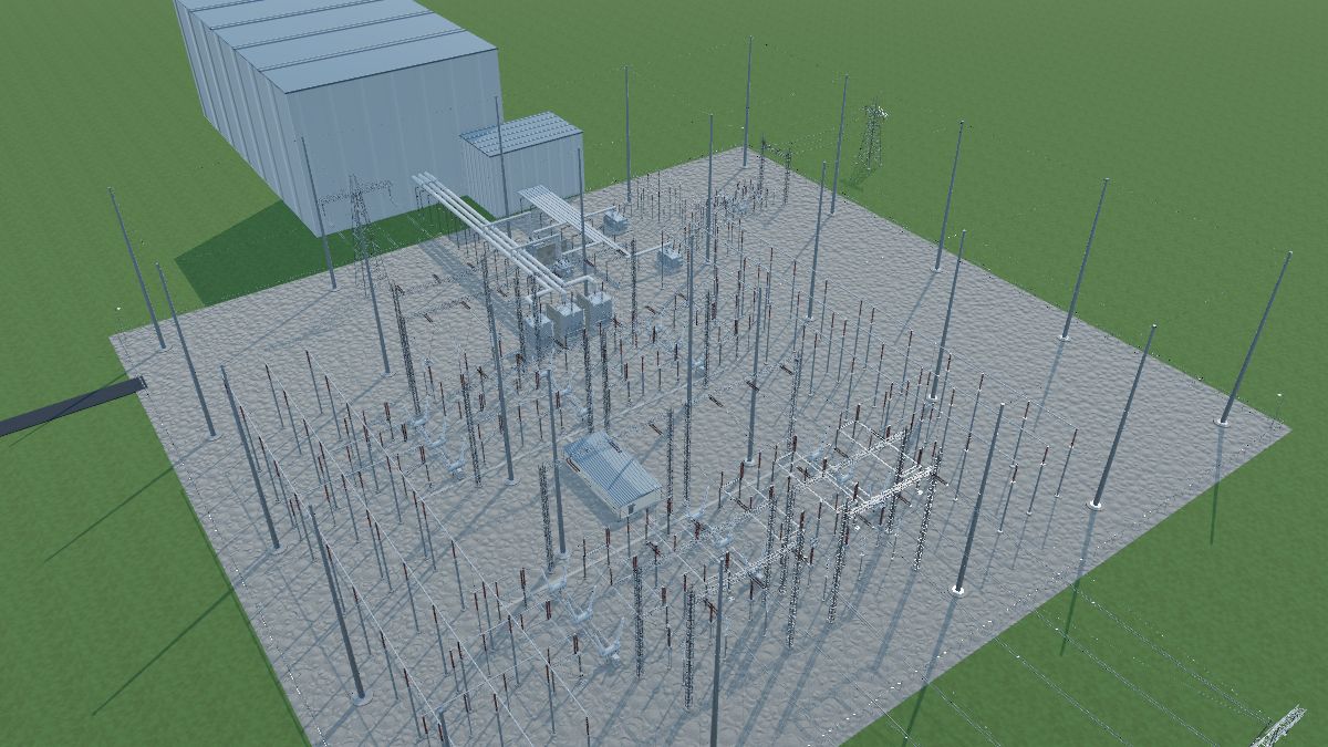
How it is arranged
Two offsite circuits. The plant takes power from the grid two independent ways: back through the 500 kV yard, the step-up bank and the unit auxiliary transformers when the generator breaker is open, and through the reserve auxiliary transformers on the separate 230 kV line. That is the requirement of 10 CFR 50 Appendix A, GDC 17.
Breaker-and-a-half: each diameter runs from bus 1 to bus 2 through three breakers. Diameter 1 serves the unit and Line 1, diameter 2 serves Lines 2 and 3. Every circuit is fed by two breakers, so any one breaker or bus can be out without losing a circuit.
Generator path: generator → isolated phase bus → generator breaker (GCB) → unit auxiliary transformer taps → step-up bank low side (delta) → high side (grounded wye) → breakers 5011 and 5012.
What is not shown: the turbine and annex buildings are context massing here, and the 6.9 kV switchgear is on the one-line only. Ratings are model values for a generic plant.
Walk through it
The guided tour in the trainer stops at each of these, highlights the equipment and explains it.
- Two 500 kV buses frame the switchyard. At 500 kV the phases are about 9 m apart and the bus sits 18 m up (model values). Each diameter phase runs low under the buses and rises straight up to its own bus phase.
- 5011 is the bus 1 breaker of diameter 1. The unit is fed by 5011 and 5012, so one breaker can be maintained with the unit still on line.
- The main step-up bank: three single-phase transformers, 500 MVA each, from 24 kV delta to 500 kV grounded wye. Firewalls separate the units, and a spare unit is kept on site.
- The isolated phase bus carries the generator output: 1,375 MVA at 24 kV is about 33,000 A. Each phase has its own grounded enclosure.
- The generator breaker opens on a generator trip. The step-up bank stays energized from the grid, so the unit auxiliary transformers keep feeding the plant.
- Two unit auxiliary transformers step 24 kV down to 6.9 kV. Each has two secondary windings, one per 6.9 kV bus.
- Two reserve auxiliary transformers, fed by the separate 230 kV line: the second offsite circuit. They carry the 6.9 kV buses if the normal supply is lost.
- Non-segregated bus duct carries each 6.9 kV winding to the switchgear in the annex building.
- Lines leave from the tap points between breakers. A strung cross bus on two gantries carries each circuit out over its diameter, one phase per plane, so no conductor passes close to another phase. Line 1 shares diameter 1 with the unit.
- Masts shield the yard by the rolling-sphere method. The 500 kV bus needs tall masts because it sits high and the bays are far apart.
- Every line has two independent protection systems: line differential (87L) over the line fiber, and distance with ground overcurrent (21 / 67N). The step-up bank and each auxiliary transformer have a differential panel and a backup panel, each bus has its differential (87B), and every breaker has breaker failure (50BF). The generator's own protection is in the plant.
Switching practice
Clearance tasks you can run here with Switching and tag-out: open, tag, test and ground, with an arc flash if you get the order wrong.
- Breaker 5012 maintenance with no outage
- Clear 500 kV Line 1
- Reserve line breaker 2R1 maintenance
Equipment in this building
Each item links to its entry in the equipment reference. In the trainer, click any of them to see what it does, its ratings and its safety note.
Buchholz / gas accumulation relay × 3Conservator tank × 3Cooling fan × 64Dehydrating breather × 3Generator step-up (GSU) transformer × 3Load tap changer (LTC) compartment × 4Nameplate × 7Nitrogen gas cabinet × 4Oil valves × 7Pressure relief device × 7Radiator bank × 14Reserve auxiliary transformer × 2Sudden-pressure relay (63SP) × 4Temperature & level gauges × 7Transformer control cabinet × 7Unit auxiliary transformer × 2Dead-tank circuit breaker × 9Disconnect switch × 16Generator circuit breaker × 1Grounding switch × 20Operating mechanism cabinet × 9SF6 gas density monitor × 27Switch blade × 48Switch operator × 32Bushing current transformer × 54Coupling capacitor voltage transformer (CCVT) × 12Current transformer (CT), freestanding × 3Line trap (wave trap) × 4Potential transformer (PT / VT) × 3Surge arrester × 42Surge counter / leakage monitor × 15Bus support fitting × 84Bushing (breaker / recloser) × 54Expansion fitting × 6Flexible jumper (strain bus) × 192Grading (corona) ring × 15Isolated phase bus (IPB) × 1Non-segregated phase bus duct × 1Rigid bus × 36Shield (overhead ground) wire × 5Station post insulator × 276Strain (dead-end) insulator × 36Suspension insulator × 12Tee connector × 57Terminal connector × 294Transformer bushing × 37Transmission line conductor × 4Bus support structure × 132Concrete foundation × 403Dead-end structure × 12Equipment support stand × 181Firewall × 2Lightning mast × 25Oil containment pit × 5Transmission tower × 4Exothermic weld × 1Gate bonding jumper × 2Ground connector × 1Ground grid × 1Ground riser / pigtail × 1Ground rod × 1Neutral grounding conductor × 3Operator ground mat × 16Cable tray × 1Cable tray support × 1Cable trench × 1Conduit × 1Conduit coupling / adapter × 1Conduit elbow (sweep) × 1Control cable × 1Junction / terminal box × 22Trench cover × 1AC / DC distribution panels × 1Annex building × 1Battery charger × 1Control house × 1Eyewash station × 1HVAC unit × 1Protective relay panel × 24SCADA RTU / automation controller × 1Station battery × 1Turbine building × 1Access road × 1Area light × 4Crushed rock surface × 1Gate × 1Switchyard fence × 1Warning sign × 33
Part of a generic plant built for training. It is not any real plant or design, and sizes and ratings are model values, not design values.