1,800 rpm turbine-generator | 1,375 MVA | seven feedwater heater stages
Turbine building
Where the steam does its work. One high-pressure and three low-pressure turbines spin a 1,375 MVA generator at 1,800 rpm. Below them, the condenser turns the exhaust back to water, and the heaters, deaerator and feedwater pumps send it back to the steam generators. Turn on X-ray to hide the walls and roof.
Open this building in 3DAll buildings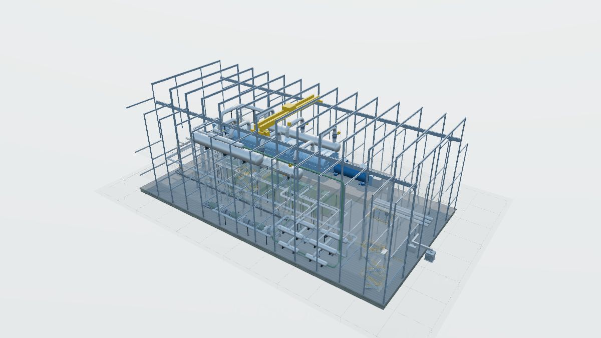
How it is arranged
Steam path: two main steam lines from the steam generators feed four stop and control valves, the double-flow HP turbine, two moisture separator reheaters, and six crossover lines (each with a reheat stop and intercept valve) to three double-flow LP turbines. Six turbine bypass valves can send 40% of full-load steam straight to the condenser.
Water path: three condenser shells and their hotwells, three 50% condensate pumps, LP heaters 1 and 2 in the condenser necks, LP heaters 3 and 4, the deaerator (heater 5), three booster and main feedwater pump sets, and HP heaters 6 and 7, then back to the steam generators through the auxiliary building.
Arrangement: the shaft line points at the nuclear island (favorable orientation for turbine missiles). The deck under the turbine-generator sits on springs. The generator leads leave through the east wall as isolated phase bus to the step-up bank in the switchyard.
Equipment counts and design data are from the public NRC description of this type of plant; sizes and layout are model values.
Walk through it
The guided tour in the trainer stops at each of these, highlights the equipment and explains it.
- The turbine building, about 387 by 210 ft (model values). The shaft points at the nuclear island, so turbine missiles would fly to the sides.
- Main steam arrives at four stop and control valves beside the high-pressure turbine.
- The double-flow high-pressure turbine. Steam enters in the middle and flows out both ends.
- Two moisture separator reheaters dry and reheat the HP exhaust before the LP turbines.
- Reheat stop and intercept valves in the six crossovers close on a trip so stored steam cannot overspeed the turbine.
- Three double-flow LP turbines with 52 in last-stage blades exhaust down into the condenser.
- The generator: 1,375 MVA, 1,800 rpm, hydrogen and water cooled.
- The turbine-generator deck sits on springs on a steel frame, isolating vibration from the building.
- Three condenser shells under the LP turbines condense the exhaust under vacuum.
- Six turbine bypass valves can dump 40% of full-load steam to the condenser on a load rejection.
- Three 50% condensate pumps take water from the hotwell.
- LP and HP feedwater heaters in the heater bay warm the water with extraction steam.
- The deaerator, high in the heater bay, strips oxygen and stores feedwater.
- Three booster and main feedwater pump sets push water back to the steam generators.
- Isolated phase bus carries the generator output out the east wall to the step-up bank.
- Cable trays turn only through factory fittings, with a radius the cables can take. Power and instrument cables run in separate trays and reach each motor and transmitter in conduit.
- The overhead crane lifts casings and rotors during outages.
Equipment in this building
Each item links to its entry in the equipment reference. In the trainer, click any of them to see what it does, its ratings and its safety note.
Excitation transformer × 1Main turbine-generator × 1Isolated phase bus (IPB) × 2Building steel frame × 1Concrete foundation × 2Equipment support stand × 1Handrail × 2Lightning protection × 1Operating floor and mezzanines × 1Stair tower × 1Turbine-generator foundation × 1Exothermic weld × 1Ground grid × 1Ground rod × 1Cable tray × 4Cable tray barrier × 2Cable tray fitting × 14Cable tray support × 151Cables in tray × 4Conduit × 27Conduit body (LB) × 5Conduit support × 93Drop-out and conduit-to-tray fittings × 26Liquidtight flexible metal conduit × 20Penetration seal (fire barrier) × 2Tray grounding conductor × 2Truck bay door × 1Turbine building × 1Access road × 1Motor-operated valve × 3Pipe support × 116Differential pressure transmitter × 2Flow nozzle × 2Instrument stand × 5Instrument tubing × 7Pressure transmitter × 3Root valve × 7Booster and main feedwater pump set × 3Circulating water piping × 4Collector and brush gear × 1Condensate and feedwater piping × 41Condensate polisher × 1Condensate pump × 3Condenser air removal piping × 14Condenser vacuum pump × 4Deaerator × 1Feedwater heater × 8Front standard and bearing pedestals × 1Generator gas and cooling skids × 3High-pressure turbine × 1Low-pressure turbine × 3Main condenser × 1Main steam and reheat piping × 38Main stop and control valves × 4Moisture separator reheater × 2Reheat stop and intercept valves × 6Static excitation system × 3Turbine building crane × 1Turbine bypass valve × 6Turbine control fluid unit × 1Turbine lube oil system × 3
Part of a generic plant built for training. It is not any real plant or design, and sizes and ratings are model values, not design values.